The Explanation of Postoperative Change of Vertebral Rotation and Rib Hump Using 3 Dimensional Finite Element Scoliosis Model
- Affiliations
-
- 1Department of Orthopaedic Surgery, College of Medicine, Seoul National University. choonki@plaza.snu.ac.kr
- 2Department of Mechanical Engineering, Dankook University.
- 3Department of Mechanical and System Design Engineering, Hongik University.
- KMID: 2209700
- DOI: http://doi.org/10.4184/jkss.2003.10.1.14
Abstract
- STUDY DESIGN: An analytical study using a mathematical 3-D finite element model for thoracic scoliosis.
OBJECTIVE
To find the important kinematics and post-operative changes of the spine and rib cage, in the corrective surgery for scoliosis, using the rod derotation method. SUMMARY OF LITERATURE REVIEW: A conventional corrective surgery for scoliosis was performed, based on empirical knowledge, and an increase in the secondary postoperative change in the rib hump, and a shoulder level imbalance, were reported. However, no analytical data exists for the kinematics and optimal correction method.
MATERIALS AND METHODS
A mathematical finite element model of a normal spine, including the rib cage, sternum, both clavicles and pelvis, was developed. Using geometric mapping, with standing radiographs and CT images, a 3-D FEM of scoliosis was reconstructed, after translating and rotating the 3-D FEM of a normal spine, with the amounts analyzed from 12 built-in digitized coordinate axes for each vertebral image. With this model, three elements; distraction, translation and derotation, in operative kinematics, were investigated by analyzing the Cobb angle, apical vertebrae axial rotation (AVAR) and thoracic kyphosis. A simulation of a segmental pedicle screw fixation, with rod derotation for scoliosis, was performed. The changes in the Cobb angle, kyphotic angle, AVAR and rib hump were compared after 0 degrees, 15 degrees, 30 degrees, 45 degrees, 60 degrees and 90 degrees rod derotations.
RESULTS
In kinematics, the vertebral rod derotation of a major curve, without rod deformation, is less influential in the correction of scoliosis, simply causing an increase in the rib hump. During the simulation, the co-action of distraction and translation, during rod insertion, has a major impact on the decrease in the Cobb angle and in the maintenance of the kyphotic angle. However, after a 30 degrees rod derotation, a decrease in the kyphosis, and increases in the rib hump and AVAR were observed.
CONCLUSIONS
The distraction and translation factors were more important in operative kinematics than the rod derotation. With excessive rod derotation, the Cobb angle progressively decreased, but increases in the secondary change in the rib hump and rotation of the apical vertebrae were found.
Keyword
MeSH Terms
Figure
-
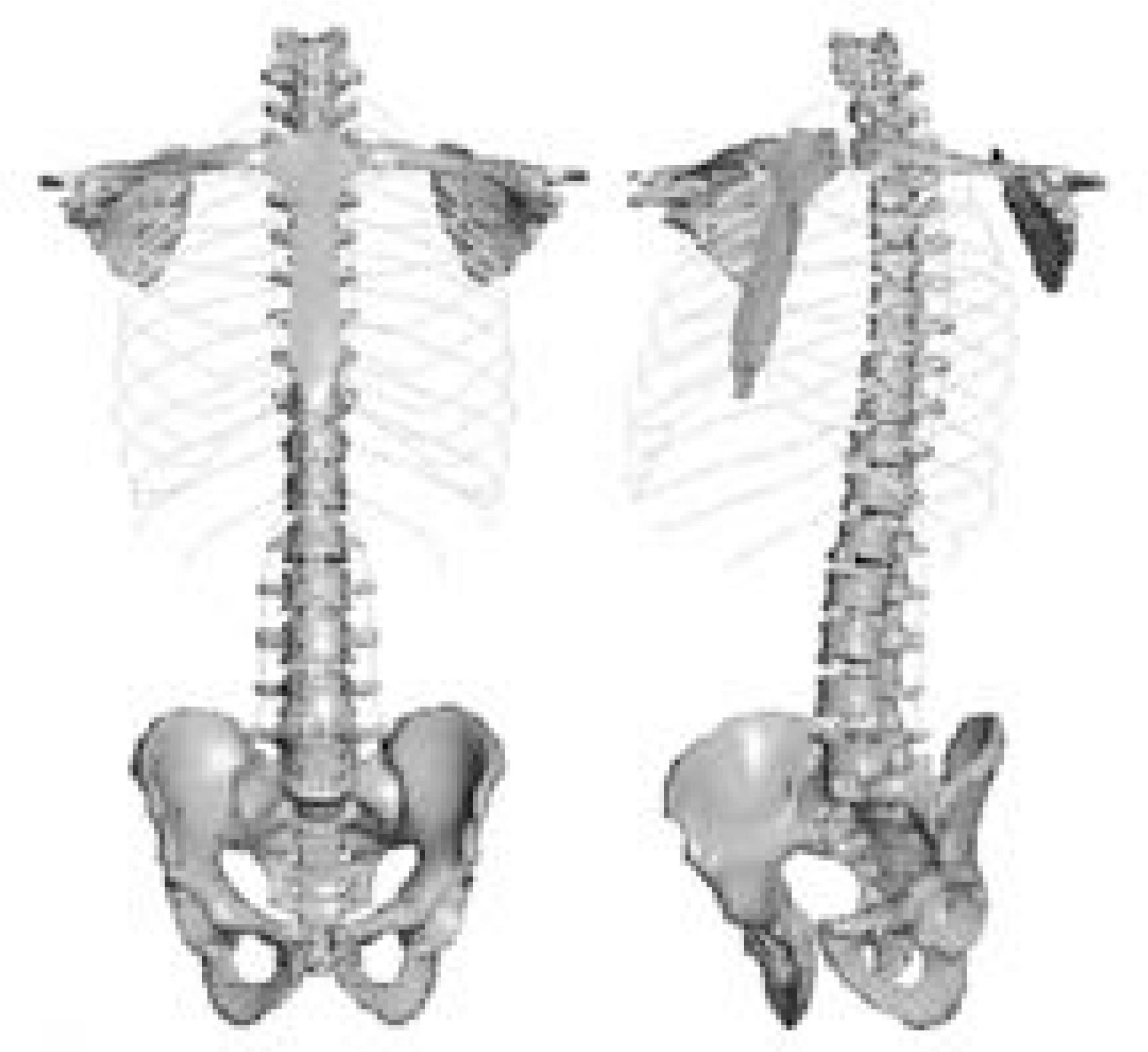
Fig. 1. Normal 3-Dimensional Spine Finite Element Model including rib cage, sternum, pelvis, clavicle, scapula, intervertebral disc and ligaments.
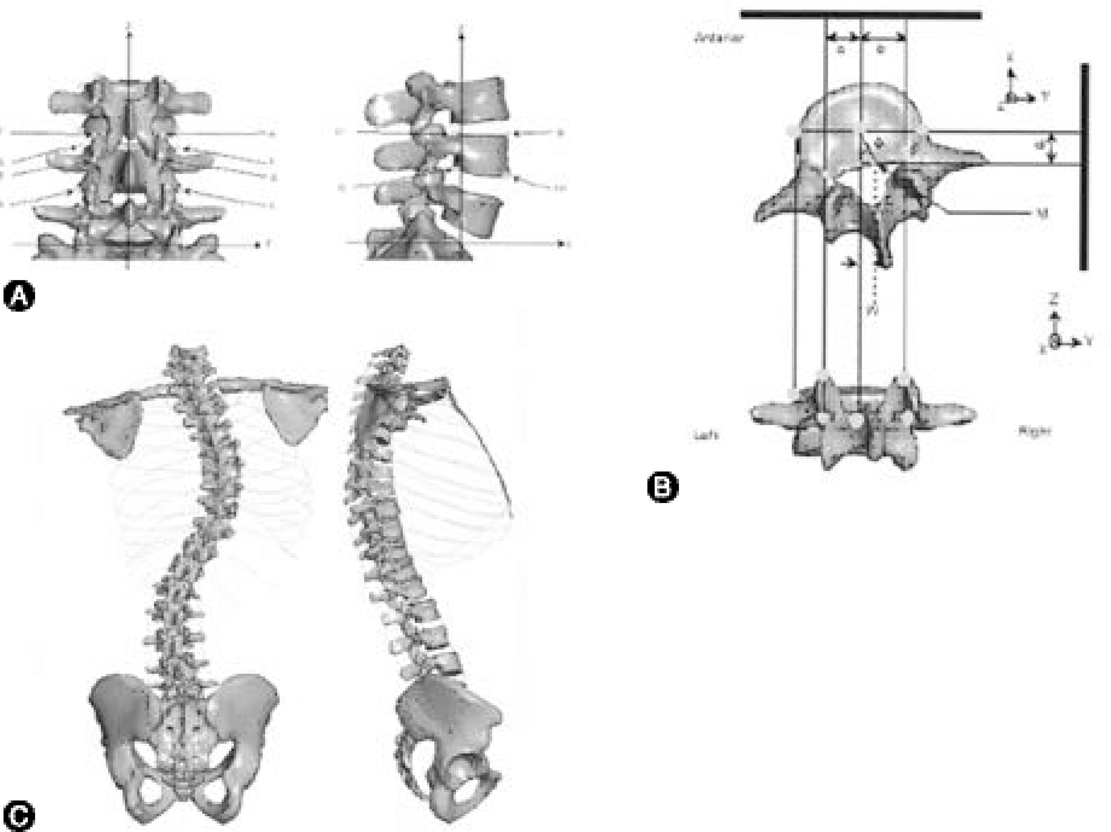
Fig. 2. A. Digitization of 12 Coordinates from roentgenogram of King-Moe type II scoliosis. B. Conversion from normal 3-D FEM spine model to scoliosis model by displacement of vertebral body center and rotation. C. Developed 3-Dimensional Scoliosis Finite Element Model similar to King-Moe type II scoliosis.

Fig. 3. Measurement of Apical Vertebrae Axial Rotation (AVAR) from 3-D FEM of scoliosis. AVAR was defined as the rotation of the apex vertebra about its local z-axis.

Fig. 4. Measurement of Rib Hump from 3-D FEM of scoliosis. The rib hump was defined as a distance between lines drawn vertically at most protruded rib surface and at opposite side of rib surface equidistant apart.
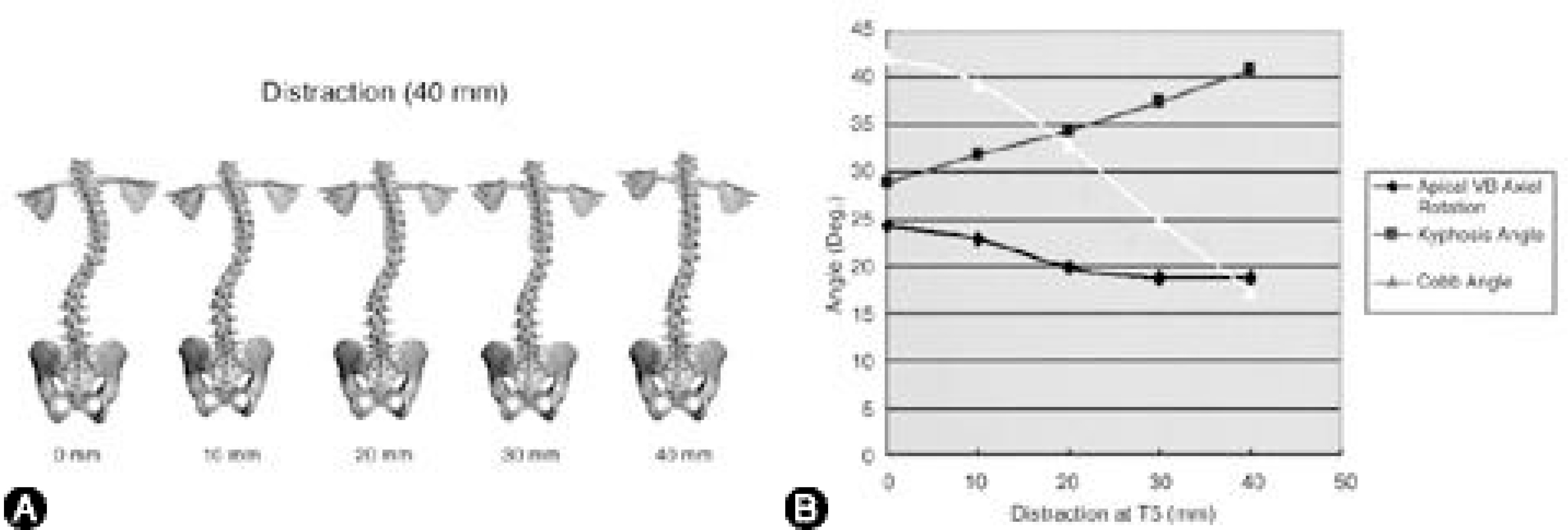
Fig. 5. A. Distraction of 3-D FEM of scoliosis. The upper end vertebra (T5) was distracted 40 mm to cranial direction. At each decadal point, 3-D FEM of scoliosis in coronal plane was displayed. B. The results of Cobb angle, angle of kyphosis, and AVAR during distraction. With distraction, Cobb angle and AVAR decreased, but the angle of kyphosis increased slightly.
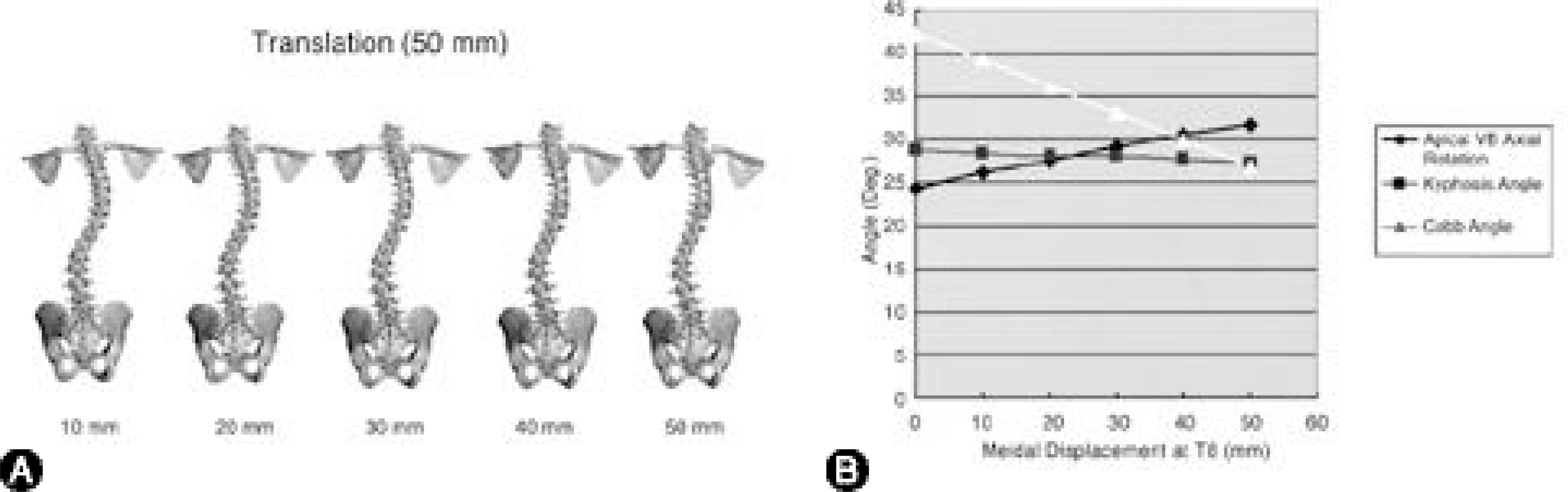
Fig. 6. A. Translation of 3-D FEM of scoliosis. The apex vertebra (T8) was translated 50 mm medially toward spinal column axis. At each decadal point until 50 mm, 3-D FEM of scoliosis in coronal plane was displayed. B. The results of Cobb angle, angle of kyphosis, and AVAR during translation. There was no change of the angle of kyphosis, but it showed a linear decrease of Cobb angle, and a slight increase of AVAR during translation.
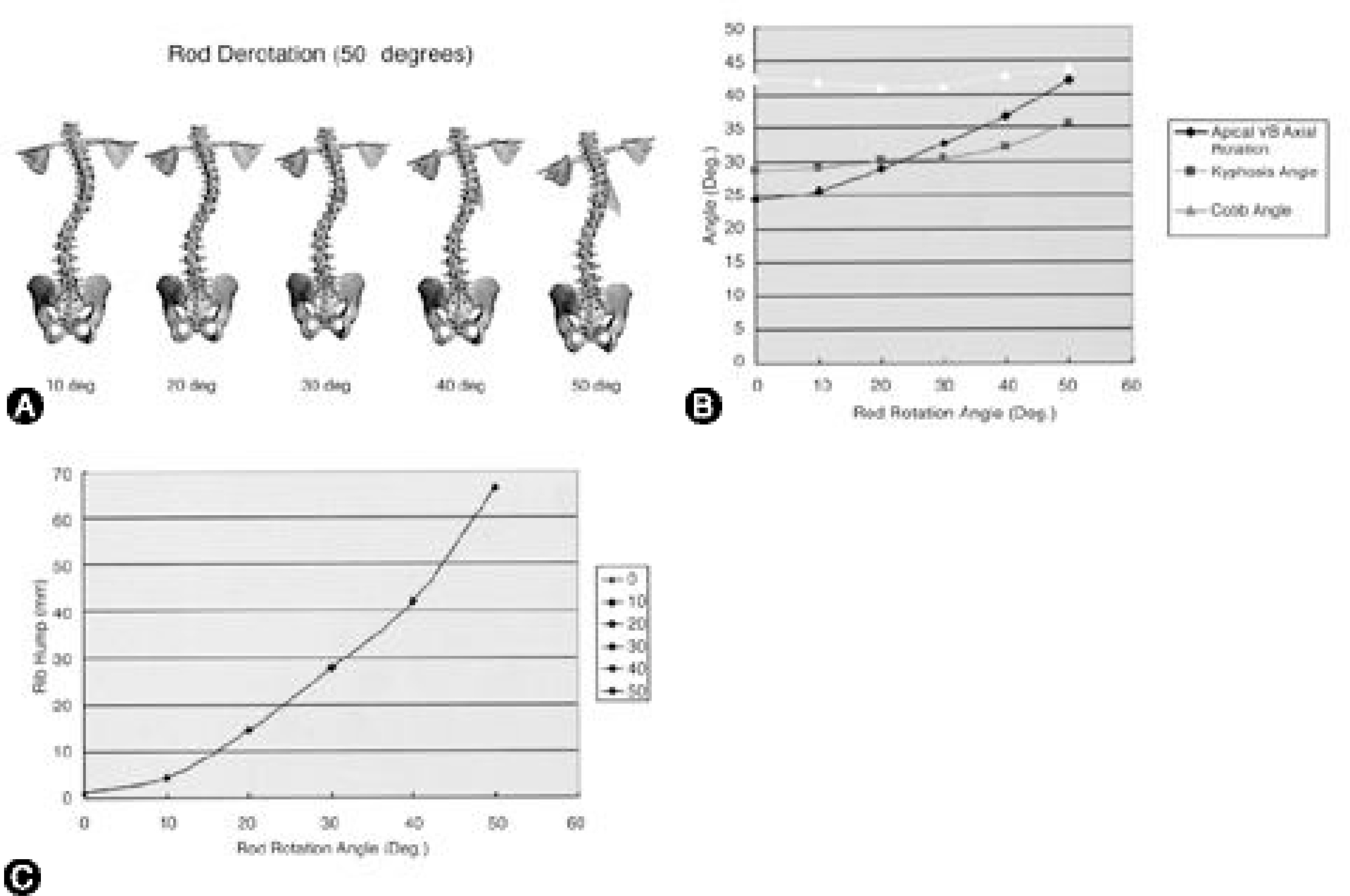
Fig. 7. A. Rotation of 3-D FEM of scoliosis. The assumptions in simulation of rod rotation are, there was no change of scoliosis curve during rod insertion and rod was deformed to fit shape of scoliosis. The inserted rod was derotated toward posteromedial direction, as it did in real operation with CD instrumentation of scoliosis. At each decadal point until 50。, 3-D FEM of scoliosis in coronal plane was displayed. B. The results of Cobb angle, angle of kyphosis, and AVAR during rod rotation. There were slight change of Cobb angle and kyphosis angle, and a linear increase of AVAR during rod rotation. C. With rod rotation, a linear increase of rib hump (about 70 mm at 50。 rotation) was observed.
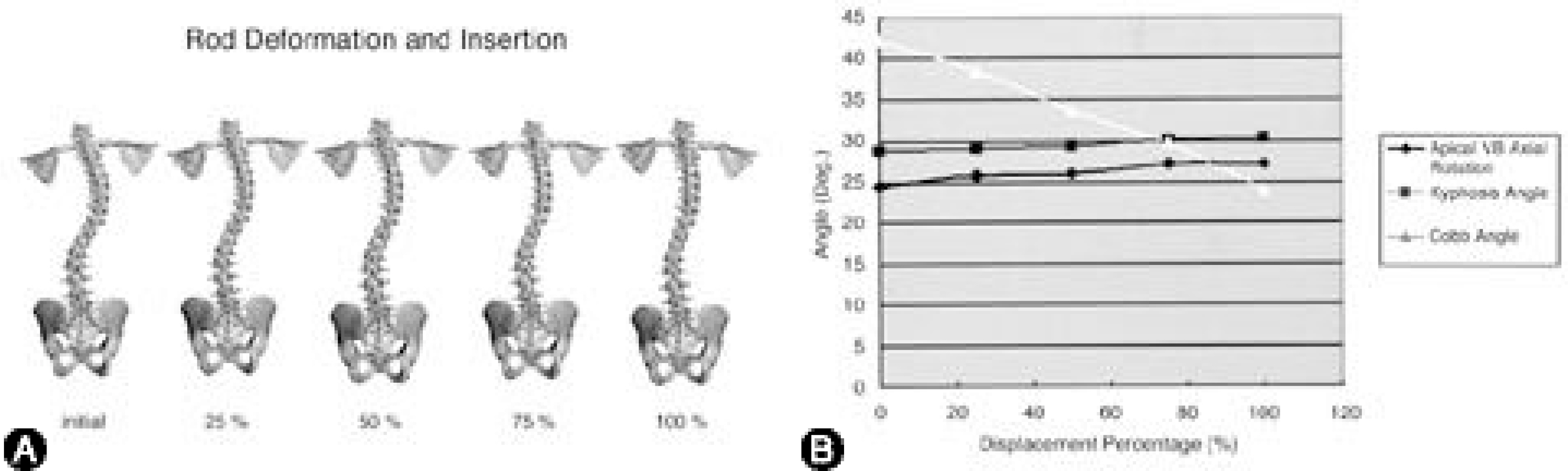
Fig. 8. A. This picture shows the change of spinal column in coronal plane during the 1st step of operative simulation. The change was divided into quarter stage. B. The results of Cobb angle, angle of kyphosis, and AVAR during 1st step of simulation. Cobb angle decreased with rod insertion, but there was a little change of kyphosis and AVAR.
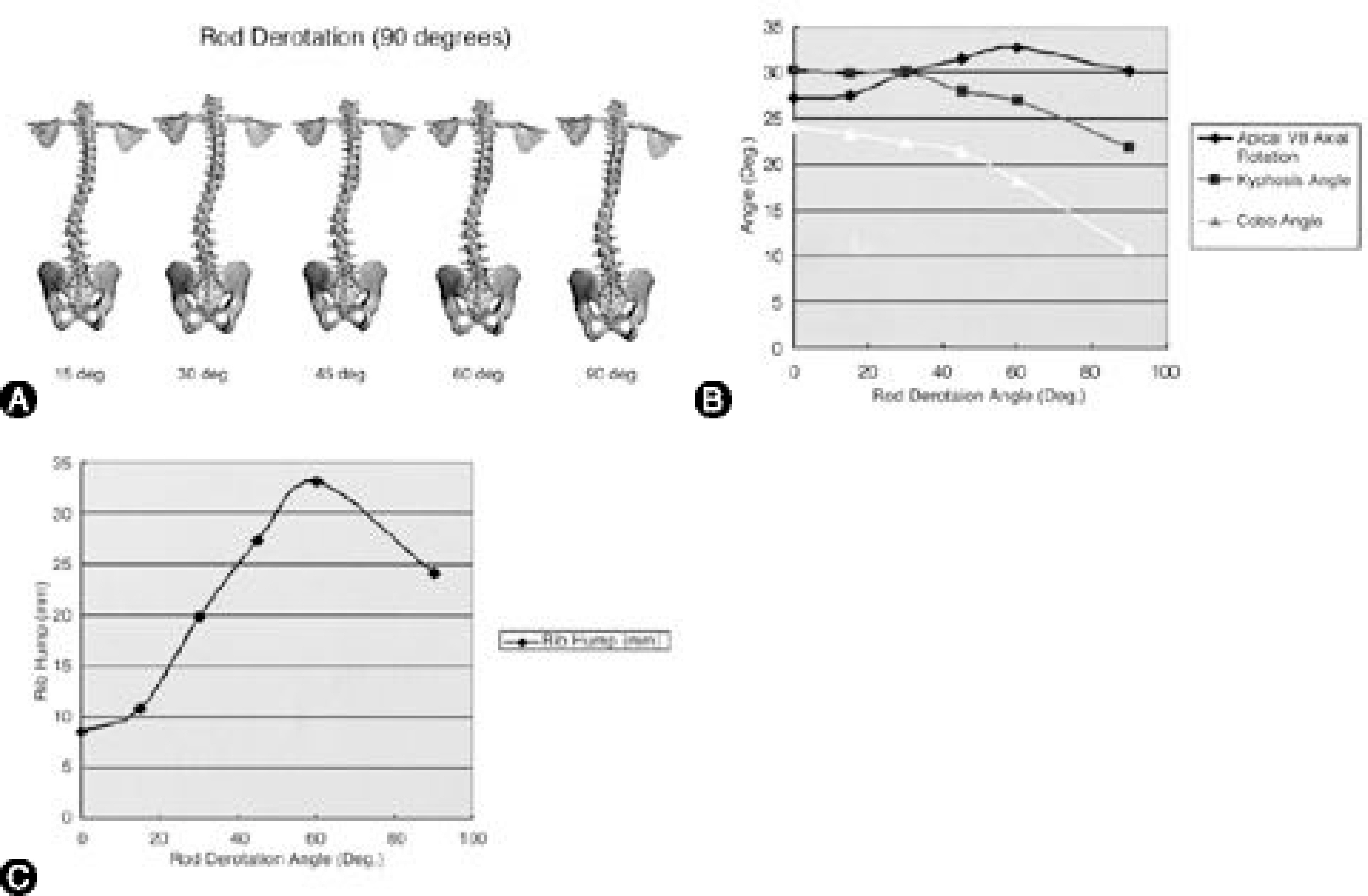
Fig. 9. A. The 2nd step of operative simulation. After rod insertion, the rod derotation toward posteromedial direction was done until 90。 . The spinal column changes in coronal plane were shown. B, C. The results of Cobb angle, angle of kyphosis, AVAR, and rib hump during 2nd step of rod derotation. Even if there was a great decrease of Cobb angle with derotation, but an associated increase of AVAR and rib hump size were found after 30o of rod derotation.
Reference
-
01). Andriacchi TP., Schultz AB., Belytschko TB., DeWald RL. Milwaukee brace correction of idiopathic scoliosis: A Biomechanical analysis and a retrospective study. J Bone Joint Surg,. 58-A:806–815. 1976.02). Asher MA., Burton DC. A concept of idiopathic scol -iosis deformities as imperfect torsion(s). Clin Orthop,. 364:11–25. 1999.03). Aubin CE., Descrimes JL., Dansereau J. Geometric modeling of the spine and thorax for biomechanical analy -sis of scoliotic deformities using finite element method. Ann Chir,. 49:749–761. 1995.04). Aubin CE., Dansereau J., de Guise J., Labelle H. A study of biomechanical coupling between spine and rib cage in the treatment by orthosis of scoliosis. Ann Chir,. 50:641–650. 1996.05). Choon-Ki Lee, Young Eun Kim, Choon-Sung Lee, Young-Mi Hong, Jun-Mo Jung and Vijay K. Goel. Impact Response of the Intervertebral Disc in a Finite-Element Model. Spine,. 25(19):2431–2439. 2000.06). Gardner-Morse M., Stokes IAF. Three-Dimensional simulations of scoliosis derotation by Cotrel-Dubousset instrumentation. J Biomech,. 27:177–181. 1993.07). Gignac D., Aubin CE., Dansereau J., Labelle H. Opti -mization method for 3D bracing correction of scoliosis using a finite element model. Eur Spine J,. 9:185–190. 2000.08). Hamilll CL., Lenke LB., Bridwell KH. The use of pedicle screw fixation to improve correction in the lumbar spine of patients with idiopathic scoliosis: Is it warranted? Spine,. 21:1241–1249. 1996.09). Harrington PR. Treatment of scoliosis. J Bone Joint Surg,. 44A:591–610. 1962.
Article10). Lenke LG., Bridwell KH., Baldus C. Cotrel-Dubous -set instrumentation for adolescent idiopathic scoliosis. J Bone Joint Surg,. 74-A:1056–1067. 1992.11). McMaster MJ. Luque rod instrumentation in the treat -ment of adolescent idiopathic scoliosis. J Bone Joint Surg,. 73-B:982–989. 1991.12). Pollock FE., Pollock FE Jr. Idiopathic scoliosis: Cor -rection of lateral and rotational deformities using the Cotrel-Dubousset spinal instrumentation system. South Med J,. 83:161–174. 1990.13). Poulin F., Aubin CE., Stokes IAF. Biom ech anica l modeling of scoliotic spine instrumentation using flexible mechanisms: Feasibility study. Ann Chir,. 52:761–767. 1998.14). Shirazi-Adle A. Nonlinear stress analysis of the whole lumbar spine in torsion: Mechanics of facet articulation. J Biomech,. 27:289–299. 1994.15). Stokes IAF., Laible J. Three-dimensional osseo-liga -mentous model of the thorax representing initiation of sco -liosis by asymmetric growth. J Biomech,. 23:589–595. 1990.16). Suk S-I., Lee C-K., Kim W-J. Segmental pedicle screw fixation in the treatment of thoracic idiopathic scol -iosis. Spine,. 20:1399–1405. 1995.17). Suk S-I., Lee S-M., Kim J-H., Kim W-J., Jung E-R., Nah K-H., Sohn H-M., Kim D-S. Decompensation in Selective Thoracic Fusion by Segmental Pedicle Screw Fixation in King type II Adolescent Idiopathic Scoliosis (AIS)-Causative Factors and its Prevention. Journal of Korean Society of Spine Surgery,. 7:571–578. 2000.18). Thompson JP., Transfeldt EE., Bradford DS., Ogilvie JW., Boachie-Adjei O. Decompensation After Cotrel-Dubousset Instrumentation of idiopathic scoliosis. Spine,. 15(9):927–931. 1990.
Article19). U Liljenqvist, U Lepsien, L Hackenberg, T Niemeyer and H Halm. Comparative analysis of pedicle screw and hook instrumentation in posterior correction and fusion of idiopathic thoracic scoliosis. Eur Spine J,. 11:336–343. 2002.20). Viviani GR., Ghista DN., Lozada PJ., Subbaraj K., Barnes G. Biomechanical analysis and simulation of scol -iosis surgical correction. Clin Orthop,. 208:40–47. 1986.
- Full Text Links
-
- Actions
-
Cited
- CITED
-
- Close
- Share
-
- Similar articles
-
- Load Distribution in Functional Spinal Unit with SB Charite III(R) Artificial Disc; Finite Element Analysis
- Stress distribution following face mask application using different finite element models according to Hounsfield unit values in CT images
- A three-dimensional finite element analysis of obturator prosthesis for edentulous maxilla
- Stress Analysis of the Lumbar Spine under Dynamic Loading Condition with 3 - D Nonlinear Finite Element Model
- Three-dimensional finite element analysis of implant-supported crown in fibula bone model
