Finite element analysis of peri-implant bone stress influenced by cervical module configuration of endosseous implant
- Affiliations
-
- 1Department of Prosthodontics, School of Dentistry, Kyungpook National University, Korea. kblee@knu.ac.kr
- 2Department of Orthodontics, School of Dentistry, Kyungpook National University, Korea.
- KMID: 2195588
- DOI: http://doi.org/10.4047/jkap.2009.47.4.394
Abstract
- STATEMENT OF PROBLEM: Crestal bone loss, a common problem associated with dental implant, has been attributed to excessive bone stresses. Design of implant's transgingival (TG) part may affect the crestal bone stresses.
PURPOSE: To investigate if concavely designed geometry at a dental implant's TG part reduces peri-implant bone stresses.
MATERIAL AND METHODS: A total of five differently configured TG parts were compared. Base model was the ITI one piece implant (Straumann, Waldenburg, Switzerland) characterized by straight TG part. Other 4 experimental models, i.e. Model-1 to Model-4, were designed to have concave TG part. Finite element analyses were carried out using an axisymmetric assumption. A vertical load of 50 N or an oblique load of 50 N acting at 30degrees with the implant's long axis was applied. For a systematic stress comparison, a total of 19 reference points were defined on nodal points around the implant. The peak crestal bone stress acting at the intersection of implant and crestal bone was estimated using regression analysis from the stress results obtained at 5 reference points defined along the mid plane of the crestal bone.
RESULTS
Base Model with straight configuration at the transgingival part created highest stresses on the crestal bone. Stress level was reduced when concavity was imposed. The greater the concavity and the closer the concavity to the crestal bone level, the less the crestal stresses.
CONCLUSION
The transgingival part of dental implant affect the crestal bone stress. And that concavely designed one may be used to reduce bone stress.
MeSH Terms
Figure
-
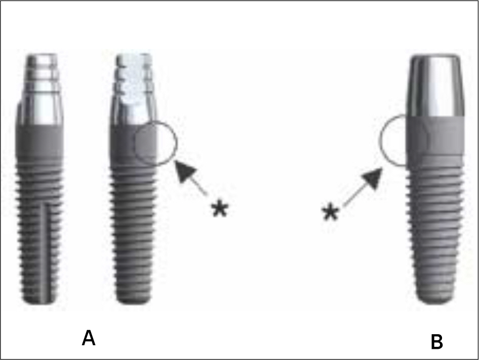
Fig. 1. A: A thin one piece implant model (NobelDirect® 3.0, TiUnite® surface-99kb). B: NobelDirect® TiUnite® surface (111 kb) for flapless surgical procedure with soft tissue integration and immediate function. ∗straight profile
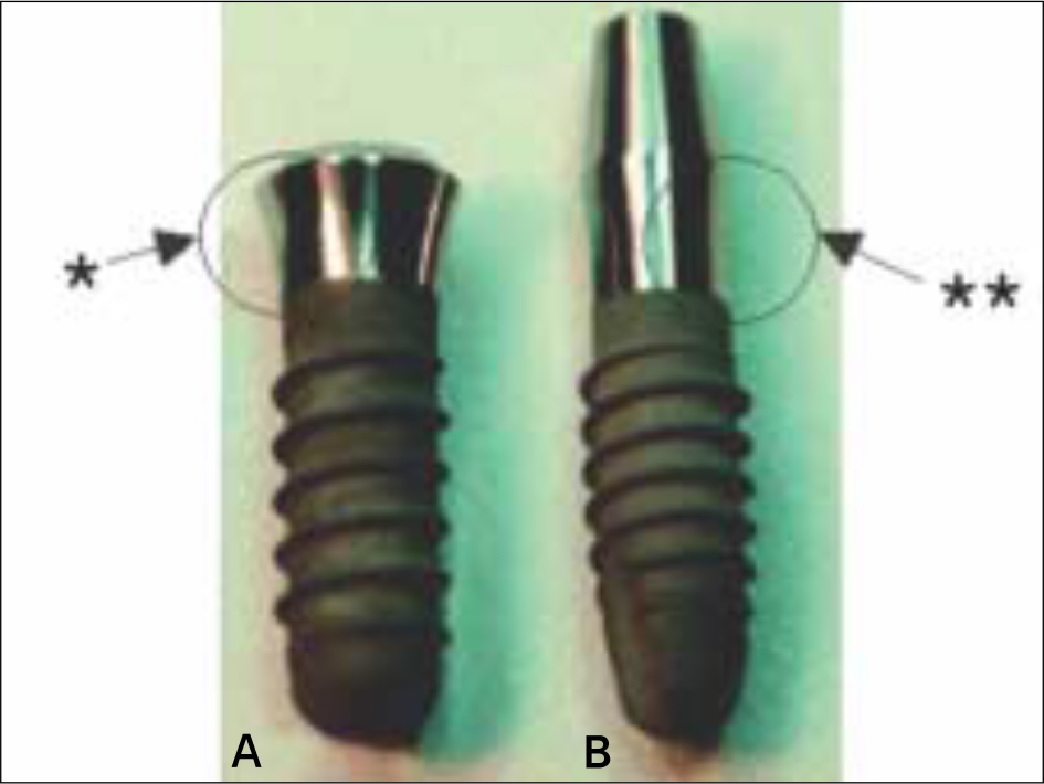
Fig. 2. Comparison of actual morse-taper 2-Piece (A) and monoblock 1-Piece ITI® implants (B) on the left and right sides, respectively. ∗concave profile, ∗∗straight profile
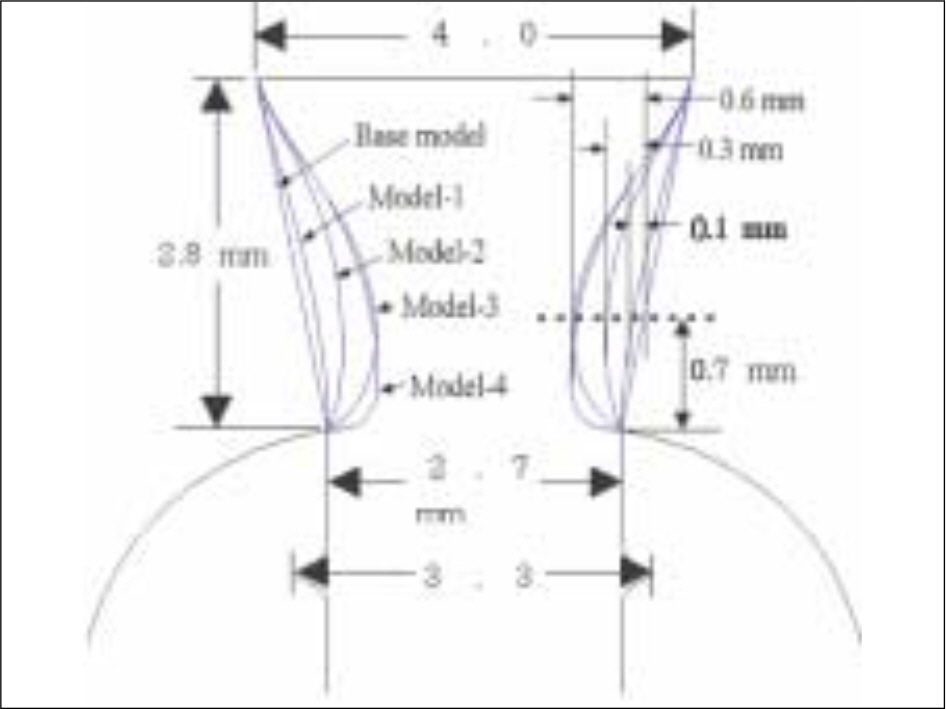
Fig. 3. Five different cervical profiles. Base model: straight line, Model-1: concavity 0.1 mm, Model-2: concavity 0.3 mm, Model-3 and Model-4: concavity 0.6 mm.
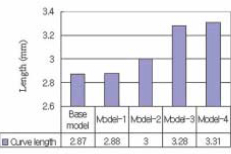
Fig. 4. Comparison of the from top to bottom curvilinear distance along the external surface of transgingival part.
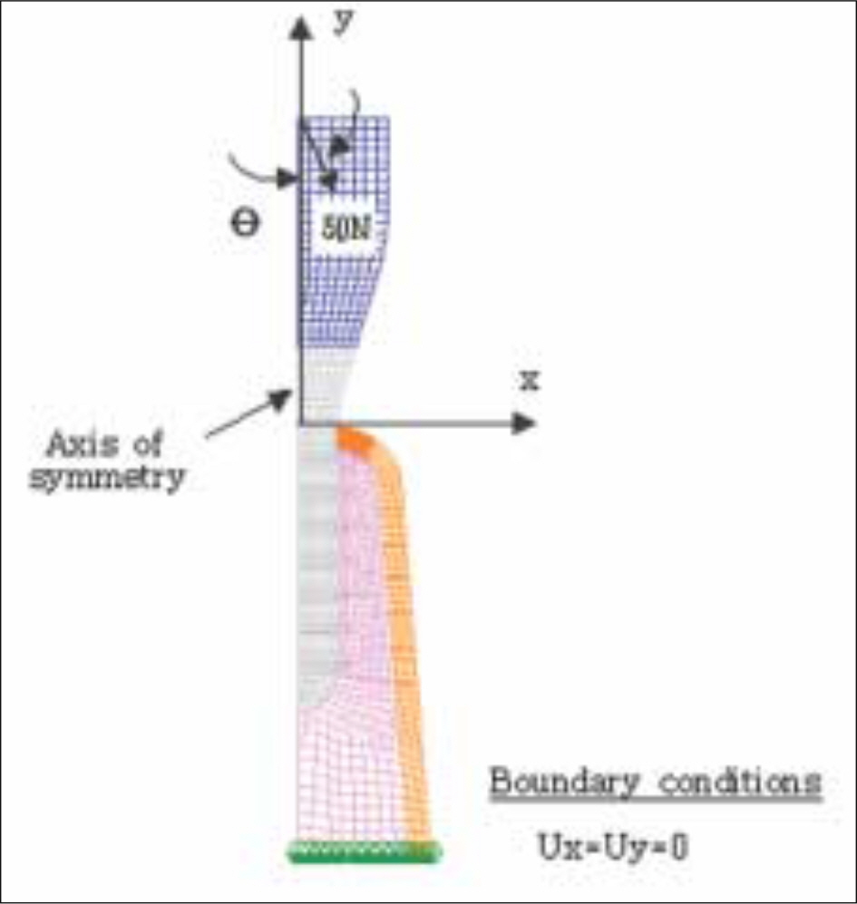
Fig. 5. A typical axisymmetric finite element mesh model (Base model). For simplicity, soft tissue is not included in the model.
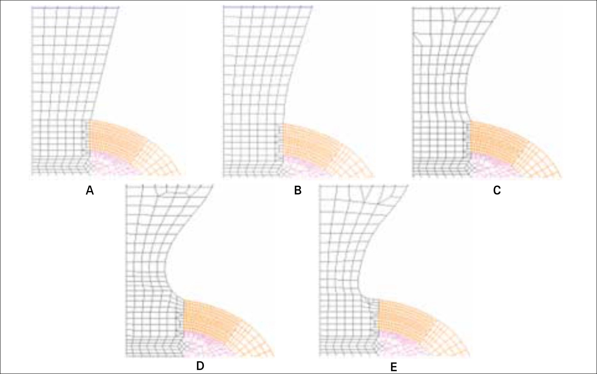
Fig. 6. The mesh model at the cervix of five different models. A: Base model, B: Model-1, C: Model-2, D: Model-3, and E: Model-4.
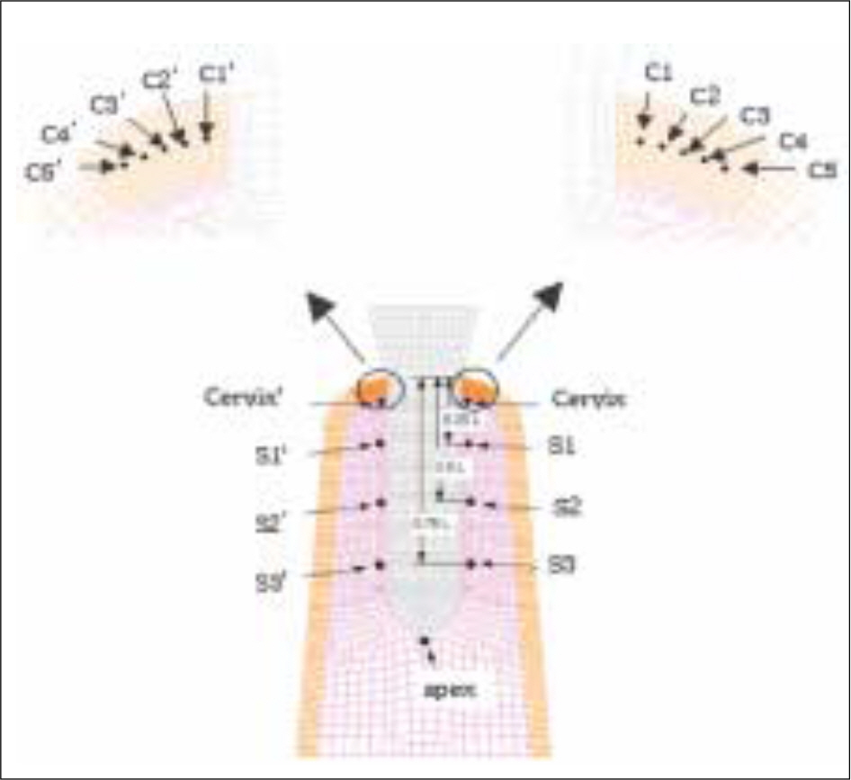
Fig. 7. Stress monitoring points; 5 points at the either of right and left sides in the mid plane of cervical cortical plate, which are 0.2, 0.4, 0.6, 0.8, and 1.0 mm distant from the bone/implant interface, and 5 points in the either side along the length of the implant, i. e. located at the cervix, 0.25 L, 0.5 L, 0.75 L and the apex. (L= length of the threaded part)
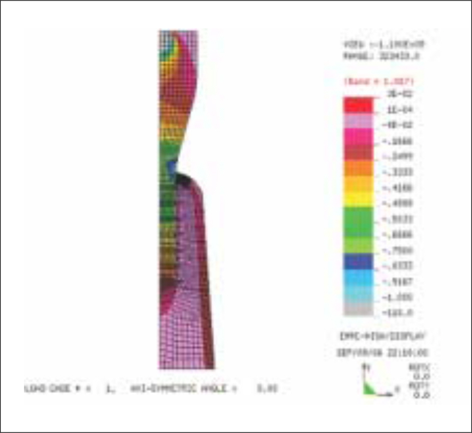
Fig. 8. Typical overall stress distribution in the implant/bone complex (Base model subject to a vertical load of 50 N).
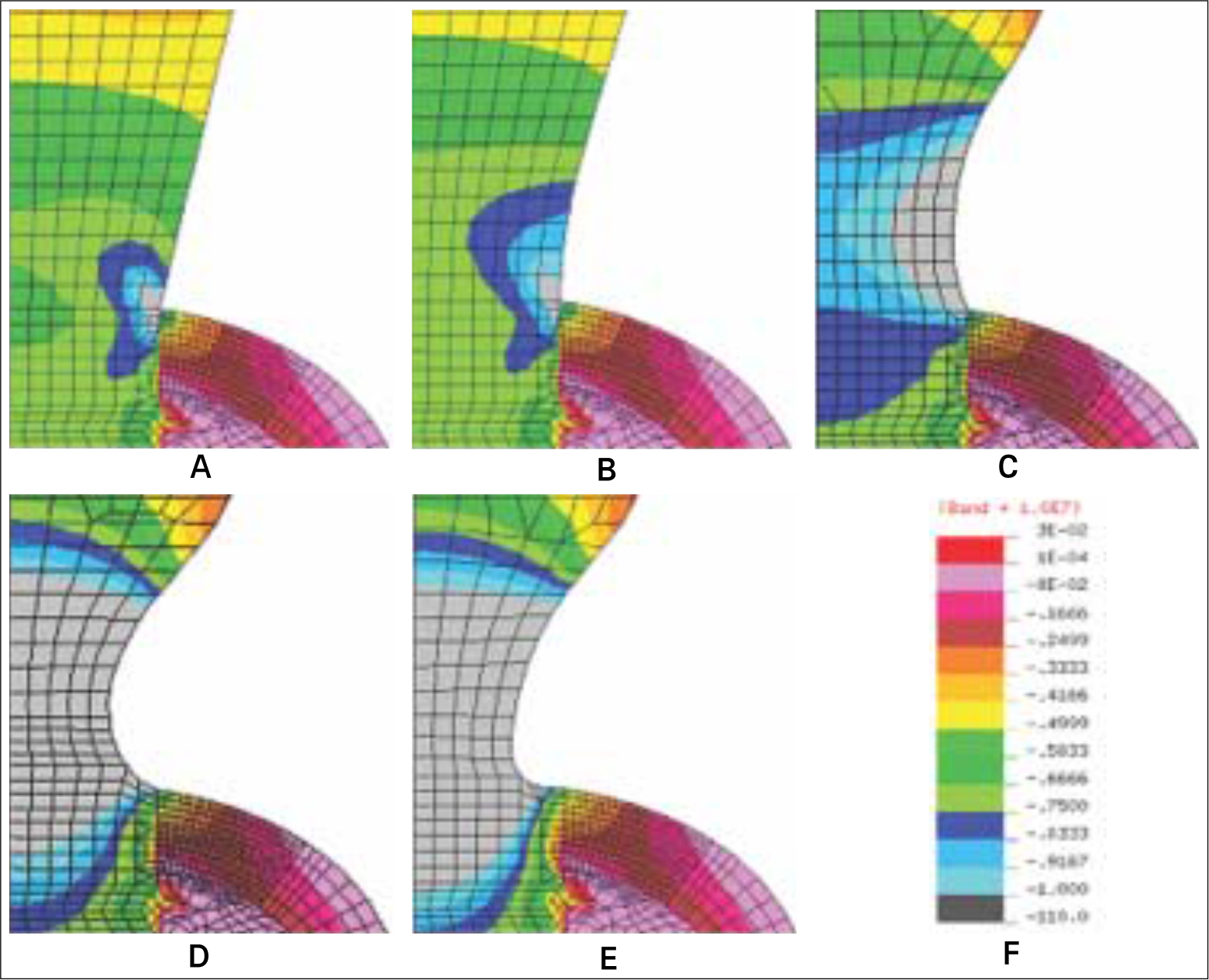
Fig. 9. Stress distribution at the cervix of five different models subject to a vertical load of 50 N. A: Base model, B: Model-1, C: Model-2, D: Model-3, and E: Model-4, F: Stress band.
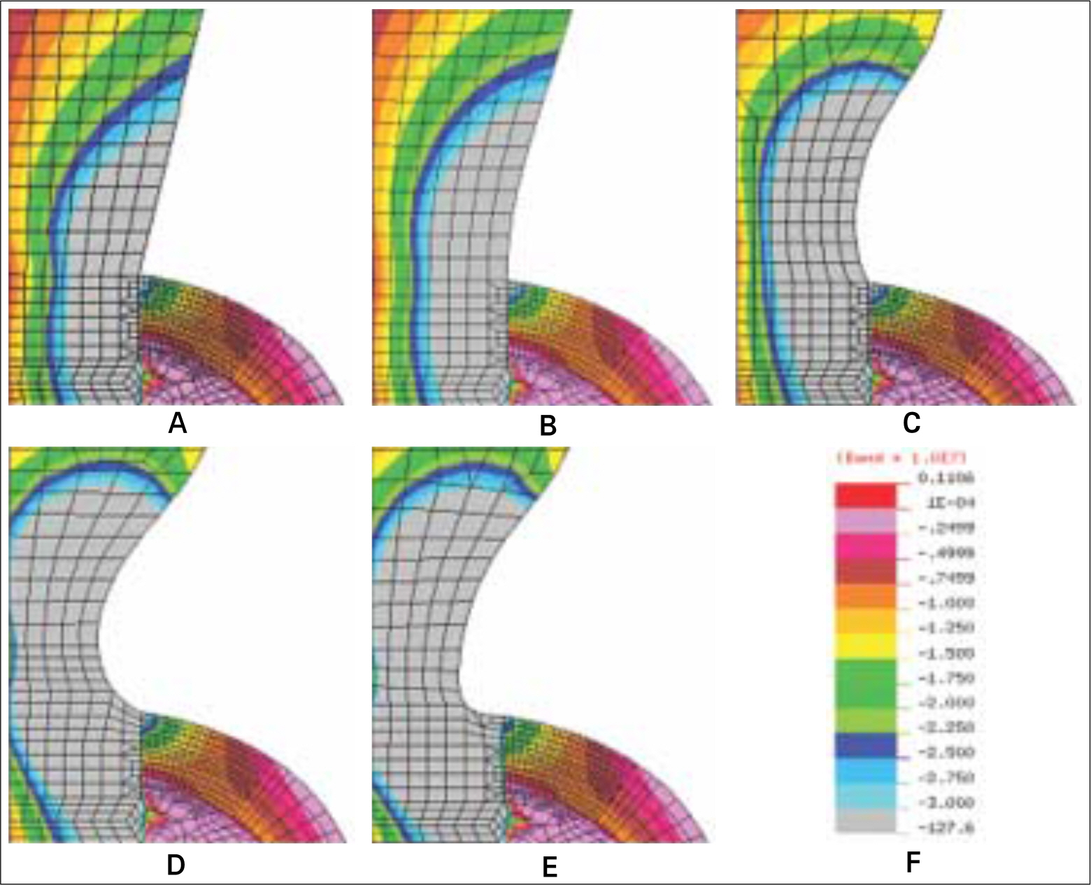
Fig. 10. Stress distribution at the cervix of five different models subject to a obliquely acting load of 50 N at an angle of 30° to the long axis of implant. A: Base model, B: Model-1, C: Model-2, D: Model-3, and E: Model-4, F: Stress band.
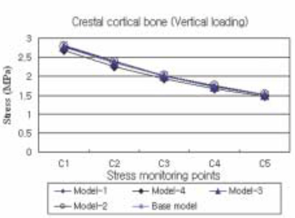
Fig. 11. The maximum compressive stress distribution in the cortical bone surrounding the five different models subject to a vertical load of 50 N.
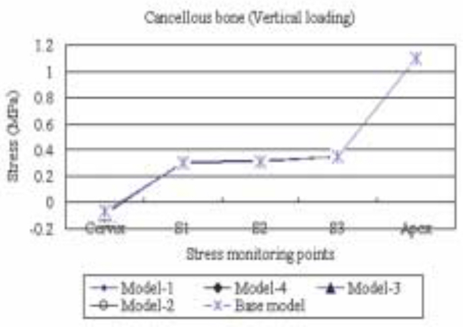
Fig. 12. The maximum compressive stress distribution in the cancellous bone surrounding the five different models subject to a vertical load of 50 N.
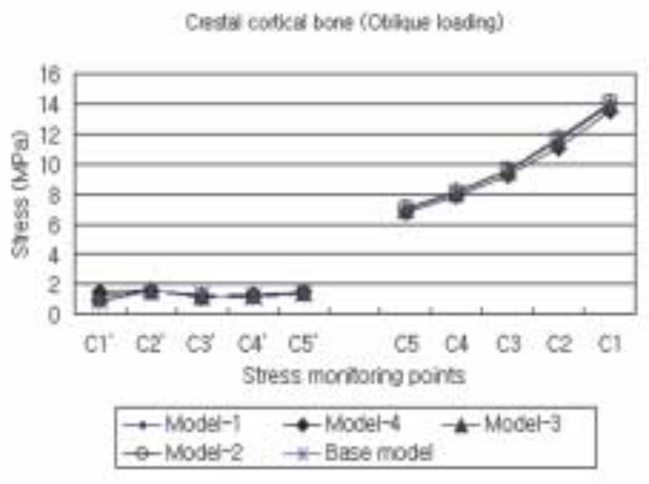
Fig. 13. The maximum compressive stress distribution in the cortical bone surrounding the five different models subject to an obliquely acting load of 50 N at 30° to the implant's long axis.
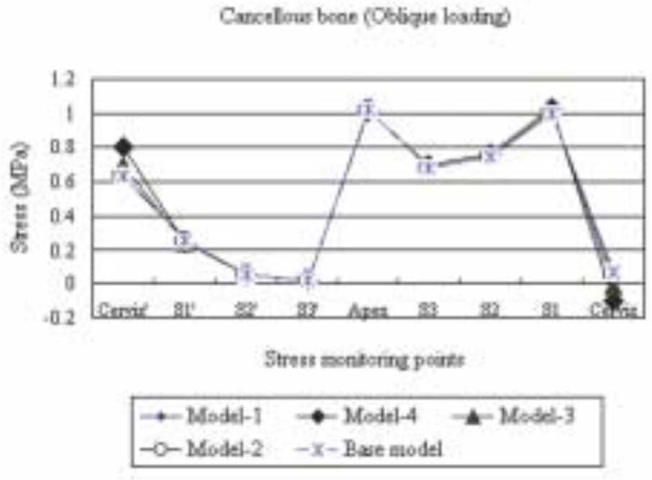
Fig. 14. The maximum compressive stress distribution in the cancellous bone surrounding the five different models subject to an obliquely acting load of 50 N at 30° to the implant's long axis.
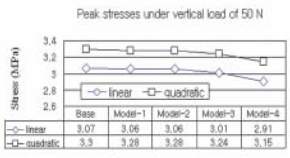
Fig. 15. The peak stress at the cervical region of five different implant models subject to a vertical load of 50 N estimated by a regression analysis.
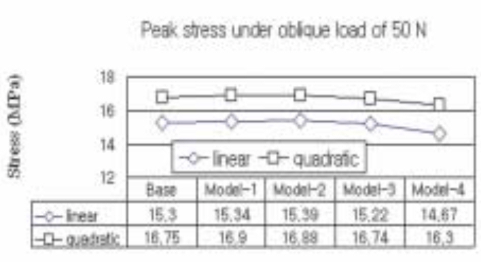
Fig. 16. The peak stress at the cervical region of five different implant models subject to an obliquely acting load of 50 N at 30° to the implant's long axis is estimated by a regression analysis.
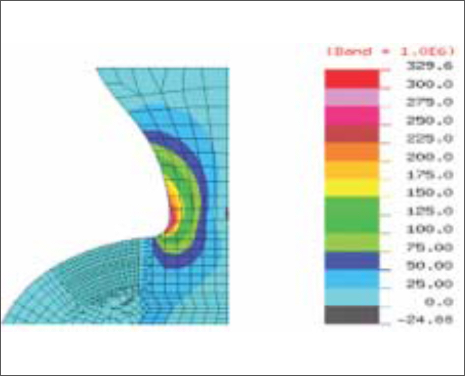
Fig. 17. Stress distribution at the implant cervix subject to an obliquely acting load of 50 N at an angle of 30° to the long axis of implant (maximum tensile stress, Model-4).
Cited by 4 articles
-
Study of a "wing-type" implant on stress distribution and bone resorption at the alveolar crest
Jong-Wook Park, Sin-Guen Kim, Dong-Won Choi, Mi-Ra Choi, Youn-Jin Yoon, Jun-Woo Park, Dong-Ju Choi
J Korean Assoc Oral Maxillofac Surg. 2012;38(6):337-342. doi: 10.5125/jkaoms.2012.38.6.337.Influence of microthread design on marginal cortical bone strain developement: A finite element analysis
Seung-Geun Chun, Jin-Hyun Cho, Kwang-Heon Jo
J Korean Acad Prosthodont. 2010;48(3):215-223. doi: 10.4047/jkap.2010.48.3.215.Influence of crestal module design on marginal bone stress around dental implant
Jung-Yoel Lim, Jin-Hyun Cho, Kwang-Heon Jo
J Korean Acad Prosthodont. 2010;48(3):224-231. doi: 10.4047/jkap.2010.48.3.224.The effect of implant system with reverse beveled platform design on marginal bone stress distribution
Ji-Young Cha, Jin-Hyun Cho, Kwang-Hun Jo
J Korean Acad Prosthodont. 2010;48(4):266-272. doi: 10.4047/jkap.2010.48.4.266.
Reference
-
1.Eriksson RA., Albrektsson T. The effect of heat on bone regeneration: an experimental study in the rabbit using the bone growth chamber. J Oral Maxillofacial Surg. 1984. 42:705–11.
Article2.Esposito M., Hirsch JM., Lekholm U., Thomsen P. Biological factors contributing to failures of osseointegrated oral implants. (II). Etiopathogenesis. Eur J Oral Sci. 1998. 106:721–64.
Article3.Covani U., Bortolaia C., Barone A., Sbordone L. Bucco-lingual crestal bone changes after immediate and delayed implant placement. J Periodontol. 2004. 75:1605–12.
Article4.Weinberg LA., Kruger B. Biomechanical considerations when combining tooth-supported prostheses. Oral Surg Oral Med Oral Pathol. 1994. 78:22–7.5.Misch CE., Suzuki JB., Misch-Dietsh FM., Bidez MW. A positive correlation between occlusal trauma and peri-implant bone loss: literature support. Implant Dent. 2005. 14:108–16.
Article6.Broggini N., McManus LM., Hermann JS., Medina RU., Oates TW., Schenk RK., Buser D., Mellonig JT., Cochran DL. Persistent acute inflammation at the implant-abutment interface. J Dent Res. 2003. 82:232–7.
Article7.Hermann JS., Buser D., Schenk RK., Cochran DL. Crestal bone changes around titanium implants. A histometric evaluation of unloaded non-submerged and submerged implants in the canine mandible. J Periodontol. 2000. 71:1412–24.
Article8.Piattelli A., Vrespa G., Petrone G., Iezzi G., Annibali S., Scarano A. Role of the microgap between implant and abutment: a retrospective histologic evaluation in monkeys. J Periodontol. 2003. 74:346–52.
Article9.Sanavi F., Weisgold AS., Rose LF. Biologic width and its relation to periodontal biotypes. J Esthet Dent. 1998. 10:157–63.
Article10.Tarnow DP., Cho SC., Wallace SS. The effect of inter-implant distance on the height of inter-implant bone crest. J Periodontol. 2000. 71:546–9.
Article11.Hartman GA., Cochran DL. Initial implant position determines the magnitude of crestal bone remodeling. J Periodontol. 2004. 75:572–7.
Article12.Oh TJ., Yoon J., Misch CE., Wang HL. The causes of early implant bone loss: myth or science? J Periodontol. 2002. 73:322–33.
Article13.Chun HJ., Cheong SY., Han JH., Heo SJ., Chung JP., Rhyu IC., Choi YC., Baik HK., Ku H., Kim MH. Evaluation of design parameters of osseointegrated dental implants using finite element analysis. J Oral Rehabil. 2002. 29:565–74.
Article14.Bozkaya D., Muftu S., Muftu A. Evaluation of load transfer characteristics of five different implants in compact bone at different load levels by finite elements analysis. J Prosthet Dent. 2004. 92:523–30.
Article15.Holmes DC., Loftus JT. Influence of bone quality on stress distribution for endosseous implants. J Oral Implantol. 1997. 23:104–11.16.Kitagawa T., Tanimoto Y., Nemoto K., Aida M. Influence of cortical bone quality on stress distribution in bone around dental implant. Dent Mater J. 2005. 24:219–24.
Article17.Petrie CS., Williams JL. Comparative evaluation of implant designs: influence of diameter, length, and taper on strains in the alveolar crest. A three-dimensional finite-element analysis. Clin Oral Implants Res. 2005. 16:486–94.18.Sevimay M., Turhan F., Kilicarslan MA., Eskitascioglu G. Three-dimensional finite element analysis of the effect of different bone quality on stress distribution in an implant-supported crown. J Prosthet Dent. 2005. 93:227–34.
Article19.Barbier L., Vander Sloten J., Krzesinski G., Schepers E., Van der Perre G. Finite element analysis of non-axial versus axial loading of oral implants in the mandible of the dog. J Oral Rehabil. 1998. 25:847–58.
Article20.Kitamura E., Stegaroiu R., Nomura S., Miyakawa O. Influence of marginal bone resorption on stress around an implant-a three-dimensional finite element analysis. J Oral Rehabil. 2005. 32:279–86.21.Natali AN., Pavan PG., Ruggero AL. Analysis of bone-implant interaction phenomena by using a numerical approach. Clin Oral Implants Res. 2006. 17:67–74.
Article22.Frost HM. A 2003 update of bone physiology and Wolff's Law for clinicians. Angle Orthod. 2004. 74:3–15.23.Melsen B. Biological reaction of alveolar bone to orthodontic tooth movement. Angle Orthod. 1999. 69:151–8.24.Clelland NL., Ismail YH., Zaki HS., Pipko D. Three-dimensional finite element stress analysis in and around the Screw-Vent implant. Int J Oral Maxillofac Implants. 1991. 6:391–8.25.Clelland NL., Gilat A. The effect of abutment angulation on stress transfer for an implant. J Prosthodont. 1992. 1:24–8.
Article26.Meijer HJ., Starmans FJ., Steen WH., Bosman F. Location of implants in the interforaminal region of the mandible and the consequences for the design of the superstructure. J Oral Rehabil. 1994. 21:47–56.
Article27.Hoshaw SJ., Brunski JB., Cochran GVB. Mechanical loading of Bra � nemark fixtures affects interfacial bone modeling and remodeling. Int J Oral Maxillofac Implants. 1994. 9:345–60.28.Isidor F. Histological evaluation of peri-implant bone at implants subjected to occlusal overload or plaque accumulation. Clin Oral Implants Res. 1997. 8:1–9.
Article29.Quirynen M., Naert I., van Steenberghe D. Fixture design and overload influence marginal bone loss and fixture success in the Branemark system. Clin Oral Implants Res. 1992. 3:104–11.30.Jung ES., Jo KH., Lee CH. A finite element stress analysis of the bone around implant following cervical bone resorption. J Korean Acad Implant Dent. 2003. 22:38–47.31.Kitamura E., Stegaroiu R., Nomura S., Miyakawa O. Biomechanical aspects of marginal bone resorption around osseointegrated implants: considerations based on a three-dimensional finite element analysis. Clin Oral Implants Res. 2004. 15:401–12.
Article32.Callan DP., Hahn J., Hogan B., Jenkins G., Krauser JT. Implant failure. Implant Dent. 2002. 11:109–17.33.Tada S., Stegaroiu R., Kitamura E., Miyakawa O., Kusakari H. Influence of implant design and bone quality on stress/strain distribution in bone around implants: a 3-dimensional finite element analysis. Int J Oral Maxillofac Implants. 2003. 18:357–68.34.Hansson S., Werke M. The implant thread as a retention element in cortical bone: the effect of thread size and thread profile: a finite element study. J Biomech. 2003. 36:1247–58.
Article35.O'Brien GR., Gonshor A., Balfour A. A 6-year prospective study of 620 stress-diversion surface (SDS) dental implants. J Oral Implantol. 2004. 30:350–7.36.Gotfredsen K., Berglundh T., Lindhe J. Bone reactions adjacent to titanium implants with different surface characteristics subjected to static load. A study in the dog (II). Clinl Oral Implants Res. 2001. 12:196–201.
Article37.Yu W., Jang YJ., Kyung HM. Combined influence of implant diameter and alveolar ridge width on crestal bone stress: a quantitative approach. Int J Oral Maxillofac Implants. 2009. 24:88–95.38.NISA II/DISPLAY III User's Manuel, Engineering Mechanics Research Corporation (EMRC).39.Borchers L. Reichart P. Three-dimensional stress distribution around a dental implant at different stages of interface development. J Dent Res. 1983. 62:155–9.40.Collings EW. The physical metallurgy of titanium alloys. Metals Park (OH): Americal society of metals;1984.41.Craig RG. Restorative dental materials. 8th ed.St. Louis (MO): Mosby;1989. p. 84.42.Nicolella DP., Lankford J., Jepsen KJ., Davy DT. Correlation of physical damage development with microstructure and strain localization in bone. Am Soc Mechanical Engineers. 1997. 35:311–2.43.Koh CS., Lee MS., Choi KW. Improved stress analyses of dental systems implant by homogenization technique. J Korean Acad Periodontol. 1997. 27:263–90.
Article44.Lavernia CJ., Cook SD., Weinstein AM., Klawitter JJ. An analysis of stresses in a dental implant system. J Biomech. 1981. 14:555–60.
Article45.Richter EJ. In vivo vertical forces on implants. Int J Oral Maxillofac Implants. 1995. 10:99–108.46.Anderson DJ. Measurement of stress in mastication. I. J Dent Res. 1956. 35:664–70.
Article47.Anderson DJ. Measurement of stress in mastication. II. J Dent Res. 1956. 35:671–3.
Article48.Hanses G., Smedberg JI., Nilner K. Analysis of a device for assessment of abutment and prosthesis screw loosening in oral implants. Clin Oral Implants Res. 2002. 13:666–70.
Article49.Sutter F., Weber HP., Sorensen J., Belser U. The new restorative concept of the ITI dental implant system: design and engineering. Int J Perio Rest Dent. 1993. 13:409–31.50.Norton MR. An in vitro evaluation of the strength of a 1-piece and 2-piece conical abutment joint in implant design. Clin Oral Implants Res. 2000. 11:458–64.51.Merz BR., Hunenbart S., Belser UC. Mechanics of the implant-abutment connection: an 8-degree taper compared to a butt joint connection. Int J Oral Maxillofac Implants. 2000. 15:519–26.52.Degidi M., Piattelli A. 7-year follow-up of 93 immediately loaded titanium dental implants. J Oral Implantol. 2005. 31:25–31.
- Full Text Links
-
- Actions
-
Cited
- CITED
-
- Close
- Share
-
- Similar articles
-
- Cervical design effect of dental implant on stress distribution in crestal cortical bone studied by finite element analysis
- THREE-DIMENSIONAL FINI6E ELEMENT ANALYSIS OF THE ENDOSSEOUS IMPLANT DESIGNS
- EFFECTS OF BONE ENGAGEMENT TYPE&IMPLANT LENGTH ON STRESS DISTRIBUTION: A THREE DIMENSIONAL FINITE ELEMENT ANALYSIS
- Finite element approach to investigate the influence of the design configuration of the ITI solid implant on the bone stresses during the osseointegration process
- Finite element analysis of fin-type implant fixtures
