Influence of crestal module design on marginal bone stress around dental implant
- Affiliations
-
- 1Department of Prosthodontics, School of Dentistry, Kyungpook National University, Daegu, Korea. khjo@knu.ac.kr
- KMID: 2195559
- DOI: http://doi.org/10.4047/jkap.2010.48.3.224
Abstract
- PURPOSE
This study was to investigate how the crestal module design could affect the level of marginal bone stress around dental implant.
MATERIALS AND METHODS
A submerged implant of 4.1 mm in diameter and 10 mm in length was selected as baseline model (Dentis Co., Daegu,Korea).A total of 5 experimental implants of different crestal modules were designed (Type I model : with microthread at the cervical 3 mm, Type II model : the same thread pattern as Type I but with a trans-gingival module, Type III model: the same thread pattern as the control model but with a trans-gingival module, Type IV model: one piece system with concave transgingival part, Type V model: equipped with beveled platform). Stress analysis was conducted with the use of axisy mmetric finite element modeling scheme. A force of 100 N was applied at 30 degrees from the implant axis.
RESULTS
Stress analysis has shown no stress concentration around the marginal bone for the control model. As compared to the control model, the stress levels of 0.2 mm areas away from the recorded implant were slightly lower in Type I and Type IV models, but higher in Type II, Type III and Type V models. As compared to 15.09 MPa around for the control model, the stress levels were 14.78 MPa, 18.39 MPa, 21.11 MPa, 14.63 MPa, 17.88 MPa in the cases of Type I, II, III, IV and V models.
CONCLUSION
From these results, the conclusion was drawn that the microthread and the concavity with either crestal or trans-gingival modules maybe used in standard size dental implants to reduce marginal bone stress.
Figure
-

Fig. 1. Schematic presentation of the implant/bone complex shown in a bucco-lingual aspect showing. A: detailed dimensions of the submerged type fixture, B: basic dimensions of the implant/bone complex.

Fig. 2. Schematic presentation showing the crestal module designs of the control and five experimental implant systems. A: submerged system (control), B: submerged system with microthread (Type I), C: 1-stage internal system with microthread (Type II), D: 1-stage internal system (Type III), E: one piece system with concave trans-gingival part (Type IV), F: submerged system with beveled platform (Type V).
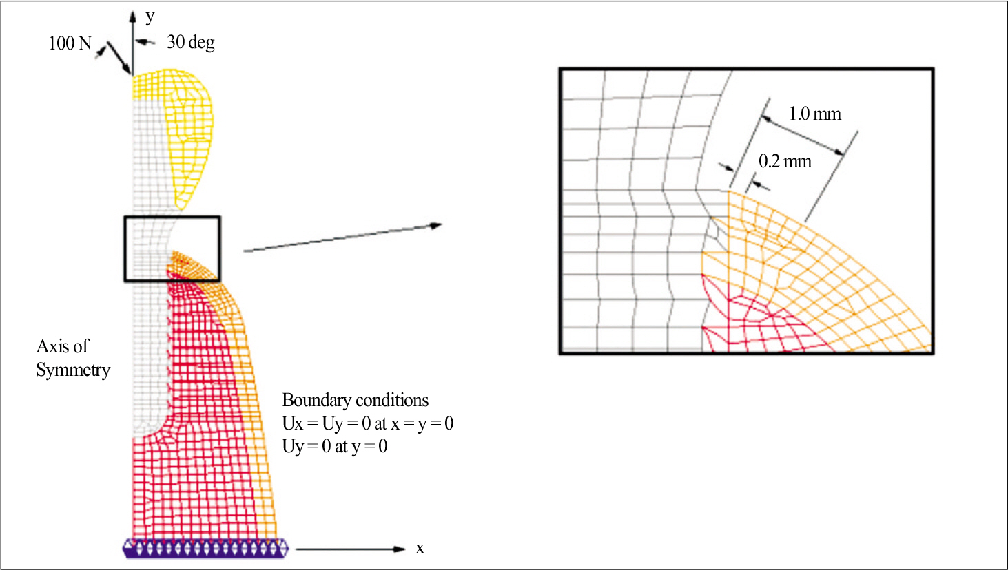
Fig. 3. Typical finite element mesh (control model). Elements sitting on the marginal bone surface within 1 mm away from the implant wall were given equal size, i.e 0.2 mm as seen in the box, in order to facilitate a direct comparison between the models analyzed.

Fig. 4. Stress distributions in the marginal bone around each of six implant models subject to a load of 100 N acting at 30 degree to the implant axis. A: control, B: Type I, C: Type II, D: Type III, E: Type IV, F: Type V, G: stress band in MPa.
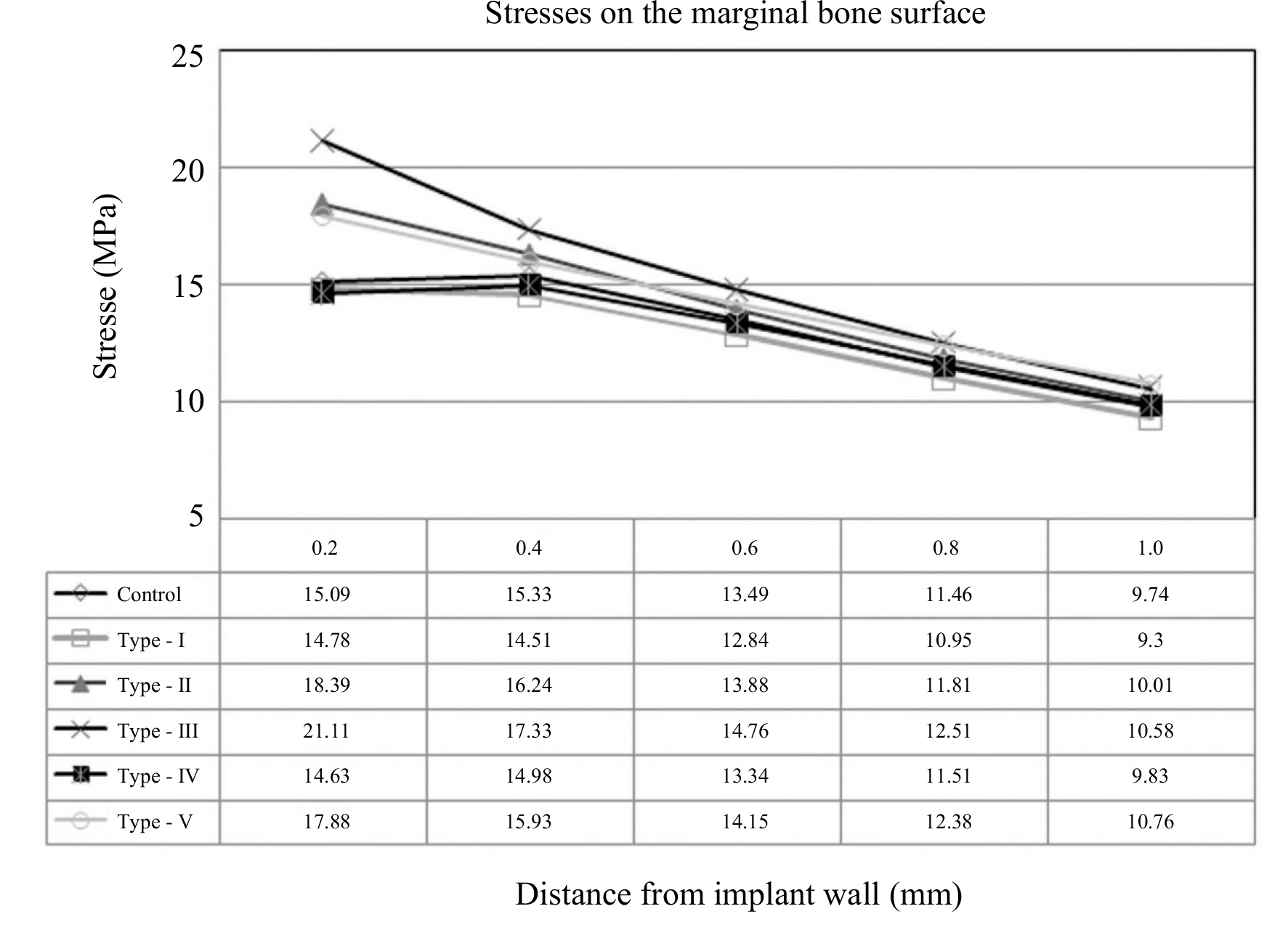
Fig. 5. Stress distribution (maximum compressive stress) on the external surface of marginal bone around the each of six implant models.
Cited by 1 articles
-
Three-dimensional finite element analysis for influence of marginal bone resorption on stress distribution in internal conical joint type implant fixture
Mi-Jung Yun, Min-Chul Yoon, Tae-Gwan Eom, Jung-Bo Huh, Chang-Mo Jeong
J Korean Acad Prosthodont. 2012;50(2):99-105. doi: 10.4047/jkap.2012.50.2.99.
Reference
-
1.Eriksson RA., Albrektsson T. The effect of heat on bone regeneration: an experimental study in the rabbit using the bone growth chamber. J Oral Maxillofac Surg. 1984. 42:705–11.
Article2.Misch CE., Suzuki JB., Misch-Dietsh FM., Bidez MW. A positive correlation between occlusal trauma and peri-implant bone loss: literature support. Implant Dent. 2005. 14:108–16.
Article3.Broggini N., McManus LM., Hermann JS., Medina RU., Oates TW., Schenk RK., Buser D., Mellonig JT., Cochran DL. Persistent acute inflammation at the implant-abutment interface. J Dent Res. 2003. 82:232–7.
Article4.Hermann JS., Buser D., Schenk RK., Cochran DL. Crestal bone changes around titanium implants. A histometric evaluation of unloaded non-submerged and submerged implants in the canine mandible. J Periodontol. 2000. 71:1412–24.
Article5.Scarano A., Assenza B., Piattelli M., Iezzi G., Leghissa GC., Quaranta A., Tortora P., Piattelli A. A 16-year study of the micro-gap between 272 human titanium implants and their abutments. J Oral Implantol. 2005. 31:269–75.
Article6.Piattelli A., Vrespa G., Petrone G., Iezzi G., Annibali S., Scarano A. Role of the microgap between implant and abutment: a retrospective histologic evaluation in monkeys. J Periodontol. 2003. 74:346–52.
Article7.Sanavi F., Weisgold AS., Rose LF. Biologic width and its relation to periodontal biotypes. J Esthet Dent. 1998. 10:157–63.
Article8.Tarnow DP., Cho SC., Wallace SS. The effect of inter-implant distance on the height of inter-implant bone crest. J Periodontol. 2000. 71:546–9.
Article9.Hartman GA., Cochran DL. Initial implant position determines the magnitude of crestal bone remodeling. J Periodontol. 2004. 75:572–7.
Article10.Oh TJ., Yoon J., Misch CE., Wang HL. The causes of early implant bone loss: myth or science? J Periodontol. 2002. 73:322–33.
Article11.Prendergast PJ., Huiskes R. Microdamage and osteocyte-lacuna strain in bone: a microstructural finite element analysis. J Biomech Eng. 1996. 118:240–6.
Article12.Frost HM. Wolff' s Law and bone' s structural adaptations to mechanical usage: an overview for clinicians. Angle Orthod. 1994. 64:175–88.13.Tada S., Stegaroiu R., Kitamura E., Miyakawa O., Kusakari H. Influence of implant design and bone quality on stress/strain distribution in bone around implants: a 3-dimensional finite element analysis. Int J Oral Maxillofac Implants. 2003. 18:357–68.14.Petrie CS., Williams JL. Comparative evaluation of implant designs: influence of diameter, length, and taper on strains in the alveolar crest. A three-dimensional finite-element analysis. Clin Oral Implants Res. 2005. 16:486–94.15.Ha ¨nggi MP., Ha ¨nggi DC., Schoolfield JD., Meyer J., Cochran DL., Hermann JS. Crestal bone changes around titanium implants. Part I: A retrospective radiographic evaluation in humans comparing two non-submerged implant designs with different machined collar lengths. J Periodontol. 2005. 76:791–802.16.Holmgren EP., Seckinger RJ., Kilgren LM., Mante F. Evaluating parameters of osseointegrated dental implants using finite element analysis-a two-dimensional comparative study examining the effects of implant diameter, implant shape, and load direction. J Oral Implantol. 1998. 24:80–8.
Article17.Matsushita Y., Kitoh M., Mizuta K., Ikeda H., Suetsugu T. Two-dimensional FEM analysis of hydroxyapatite implants: diameter effects on stress distribution. J Oral Implantol. 1990. 16:6–11.18.Chun HJ., Cheong SY., Han JH., Heo SJ., Chung JP., Rhyu IC., Choi YC., Baik HK., Ku Y., Kim MH. Evaluation of design parameters of osseointegrated dental implants using finite element analysis. J Oral Rehabil. 2002. 29:565–74.
Article19.Hansson S., Werke M. The implant thread as a retention element in cortical bone: the effect of thread size and thread profile: a finite element study. J Biomech. 2003. 36:1247–58.
Article20.Clelland NL., Gilat A. The effect of abutment angulation on stress transfer for an implant. J Prosthodont. 1992. 1:24–8.
Article21.Chun HJ., Shin HS., Han CH., Lee SH. Influence of implant abutment type on stress distribution in bone under various loading conditions using finite element analysis. Int J Oral Maxillofac Implants. 2006. 21:195–202.22.Gotfredsen K., Berglundh T., Lindhe J. Bone reactions adjacent to titanium implants with different surface characteristics subjected to static load. A study in the dog (II). Clin Oral Implants Res. 2001. 12:196–201.
Article23.O' Brien GR., Gonshor A., Balfour A. A 6-year prospective study of 620 stress-diversion surface (SDS) dental implants. J Oral Implantol. 2004. 30:350–7.24.Akc ¸ a K., Cehreli MC. A photoelastic and strain-gauge analysis of interface force transmission of internal-cone implants. Int J Periodontics Restorative Dent. 2008. 28:391–9.25.Bozkaya D., Muftu S., Muftu A. Evaluation of load transfer characteristics of five different implants in compact bone at different load levels by finite elements analysis. J Prosthet Dent. 2004. 92:523–30.
Article26.Kim YS., Kim CW., Jang KS., Lim YJ. Application of finite element analysis to evaluate platform switching. J Korean Acad Prosthodont. 2005. 43:727–35.27.Schrotenboer J., Tsao YP., Kinariwala V., Wang HL. Effect of mi-crothreads and platform switching on crestal bone stress levels: a finite element analysis. J Periodontol. 2008. 79:2166–72.
Article28.Hansson S. The implant neck: smooth or provided with retention elements. A biomechanical approach. Clin Oral Implants Res. 1999. 10:394–405.
Article29.Chung JM., Jo KH., Lee CH., Yu WJ., Lee KB. Finite element analysis of peri-implant bone stress influenced by cervical module configuration of endosseous implant. J Korean Acad Prosthodont. 2009. 47:394–405.
Article30.Li YF. Comparative and analysis study of peri-implant bone stress around Rescue implant and standard implant using finite element method. Masters thesis, Department of Dentistry, Graduate School, Kyungpook National University, Daegu, Korea,. 2009.31.NISA II/DISPLAY III User Manual, Engineering Mechanics Research Corporation. 1998.32.Yu W., Jang YJ., Kyung HM. Combined influence of implant diameter and alveolar ridge width on crestal bone stress: a quantitative approach. Int J Oral Maxillofac Implants. 2009. 24:88–95.33.Misch CE. Contemporary Implant Dentistry. St. Louis: Mosby;1999. p. 337.
- Full Text Links
-
- Actions
-
Cited
- CITED
-
- Close
- Share
-
- Similar articles
-
- Cervical design effect of dental implant on stress distribution in crestal cortical bone studied by finite element analysis
- Considerations in implant crestal module to preserve peri-implant tissue
- Finite element analysis of peri-implant bone stress influenced by cervical module configuration of endosseous implant
- Marginal bone loss around crestal or subcrestal dental implants: prospective clinical study
- Radiographic evaluation of the proximal bone level between two implants: A 3-year comparative study between Branemark and ITI implants in the mandibular posterior region
