Stress distribution in bone surrounding maxillary molar implants under different crown-to-fixture ratio: A 3D FEM analysis
- Affiliations
-
- 1Department of Advanced Prosthodontics, Graduate School of Clinical Dentistry, Korea University, Korea.
- 2Department of Prosthodontics, Graduate School of Dentistry, KyungHee University, Korea. krkwon@khu.ac.kr
- KMID: 2000405
- DOI: http://doi.org/10.4047/jkap.2008.46.5.479
Abstract
- STATEMENT OF THE PROBLEM: Under anatomical limitations on maxillary posterior region, a poor crown-to root ratio acting on dental implants can result in undesirable stress in surrounding bone, which in turn can cause bone defects and eventual failure of implants. PURPOSE: The purpose is to compare stress distribution due to different crown-root ratio and effect of splinting between natural teeth and implants in maxillary molar area under different loads. MATERIAL AND METHODS: Analysis of stress arising supporting bone of the natural teeth and the implant was made with 3-dimensional finite element method. The model simulated naturel teeth was made with 2nd premolar and 1st molar in the maxillary molar region (Model T). The model simulated implants placed on same positions with two parallel implants of Straumann Dental Implant cemented abutment (Model I). Each model was designed in different crown-root ratio (0.7:1, 1:1, 1.25:1) and set cement type gold crown to make it non-splinted or splinted. After that, 300 N force was loaded to each model in five ways (Load 1: middle of occlusal table, Load 2: middle of buccal cusp, Load 3: middle of lingual cusp, Load 4: horizontal load to buccal cusp of anterior abutment only, Load 5: horizontal load to middle of buccal cusp of each abutment), and stress distribution was analyzed. RESULTS AND CONCLUSION: On all occasions, stress was concentrated at the cervical region of the implant. Under load 1, 2 and 3, stress was not increased even when crown-root ratio increases, but under load 4 and 5, when crown-root ratio increases, stress also increased. There was difference in stress values between natural teeth and implants when crown-root ratio gradually increases; In case of natural teeth, splinting decreased stress under vertical and horizontal loads. In case of implants, splinting decreased stress under vertical loads 1,2 and 3, but increased maximal stress under loads 2 and 3. Under horizontal loads, splinting decreased stress, however the effect of splinting decreased under load 5 than load 4. Furthermore, the stress was increased, when crown-root ratio is 1.25:1. CLINICAL IMPLICATIONS: This limited finite element study suggests that the stress on supporting bone may be increased under non-axial loads and poor crown-root ratio. Under poor crown-root ratio, excessive stress was generated at the cervical region of the implant, and decreased splinting effect for stress distribution, which can be related to clinical failure.
Figure
-
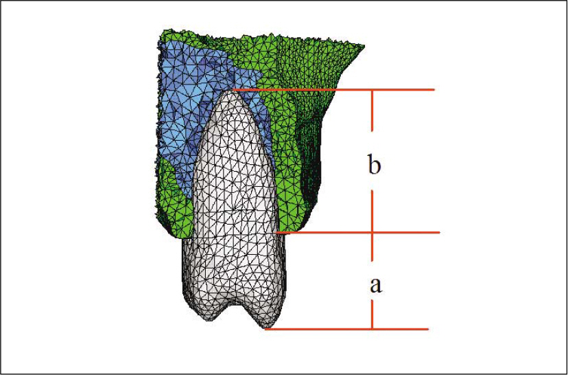
Fig. 1. Natural teeth model to Crown/Root ratio: Model T1 is 0.7:1; Model T2 is 1:1; Model T3 is 1.25:1.
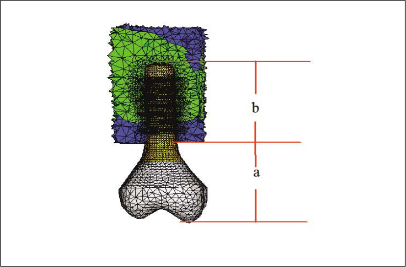
Fig. 2. Implant model to Crown/Fixture ratio: Model I1 is 0.7:1; Model I2 is 1:1; Model I3 is 1.25:1.

Fig. 3. Load conditions : buccal (left) and oblique occlusal view (right).
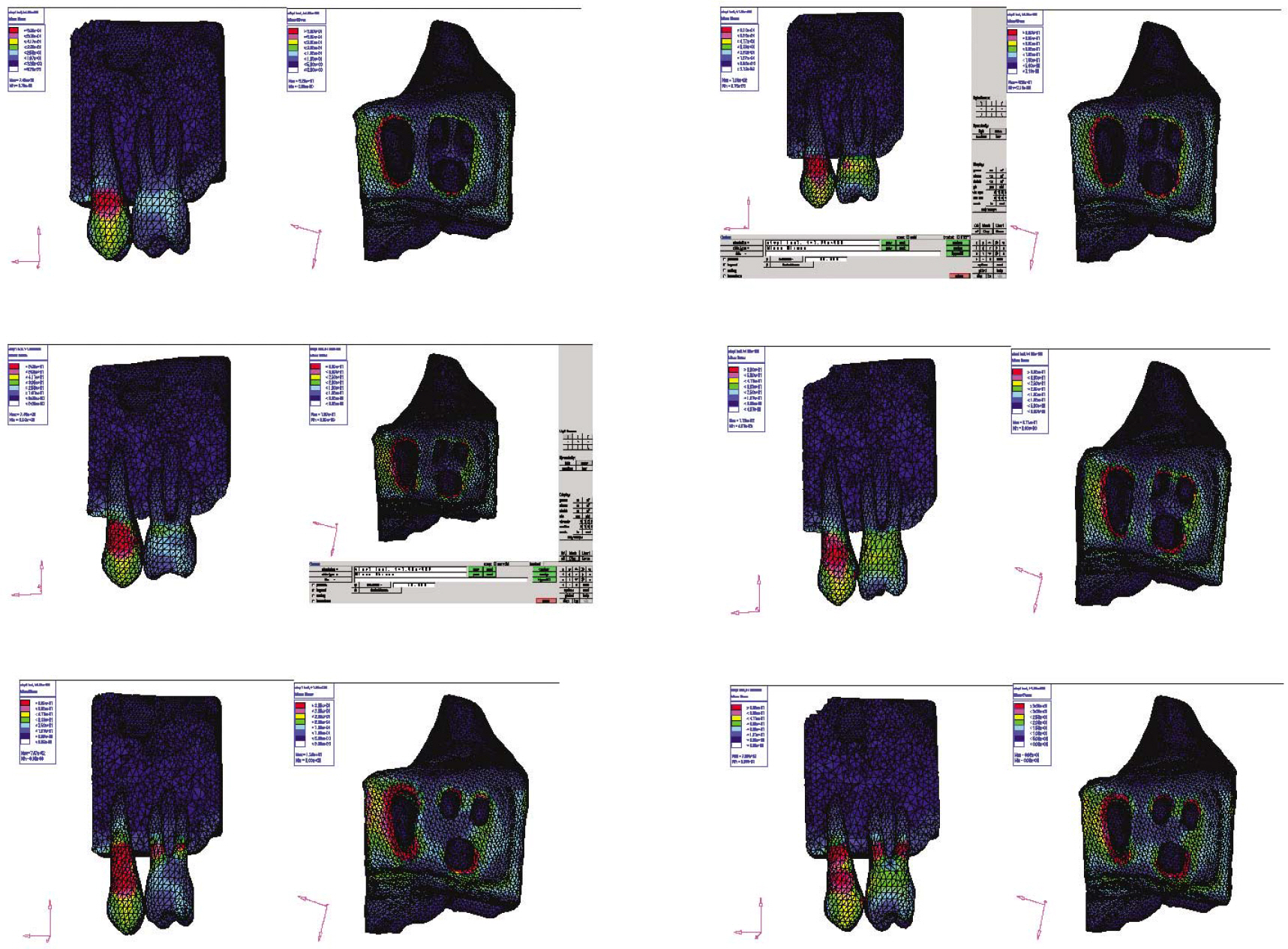
Fig. 4. Stress contour on Model T under Load condition 5: non-splinted and splinted situations (left to right); C/R ratio 0.7:1, 1:1, 1.25:1 (top to bottom).
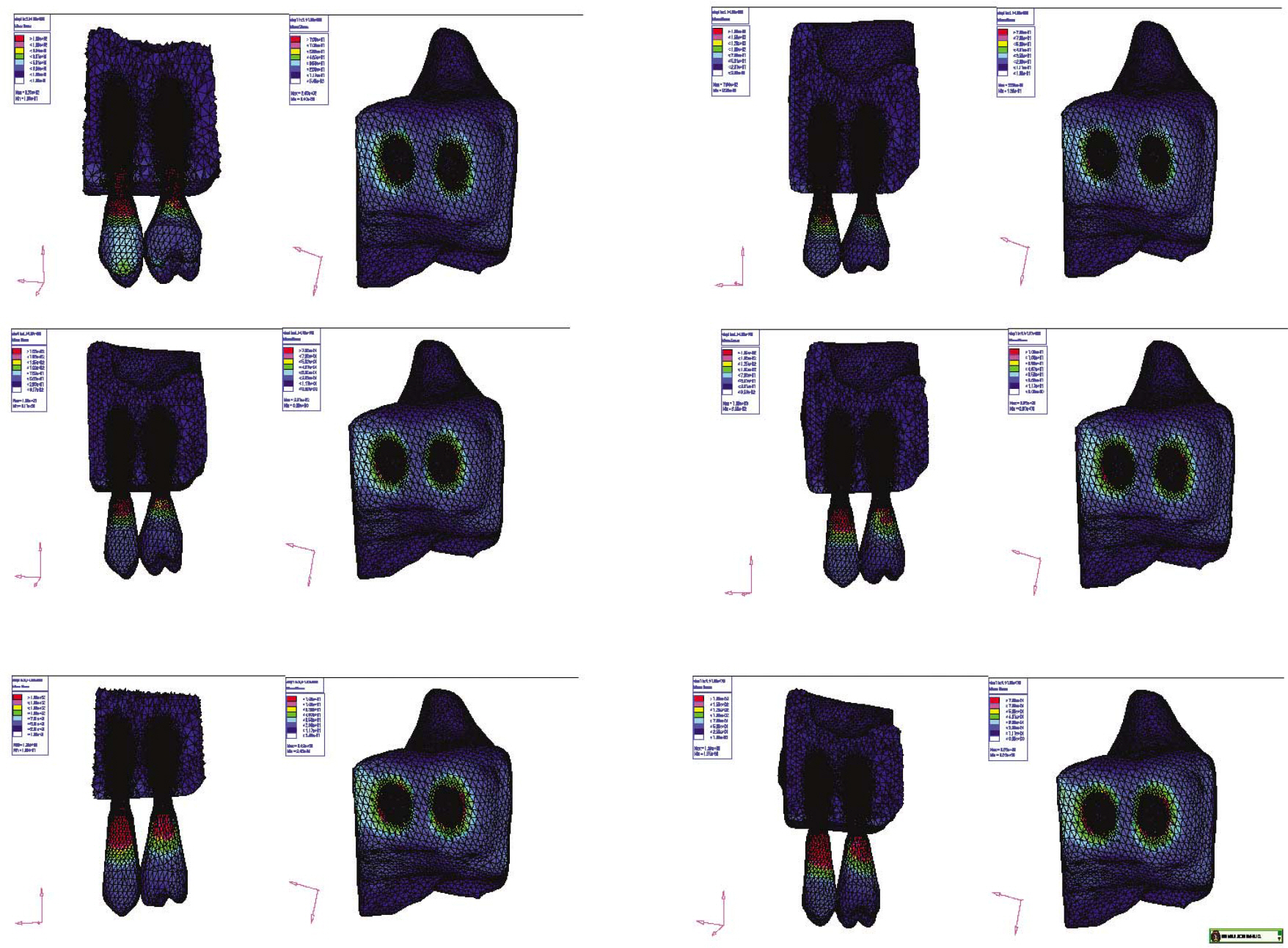
Fig. 5. Stress contour on Model I under Load condition 5: non-splinted and splinted situations (left to right); C/R ratio 0.7:1, 1:1, 1.25:1 (top to bottom).
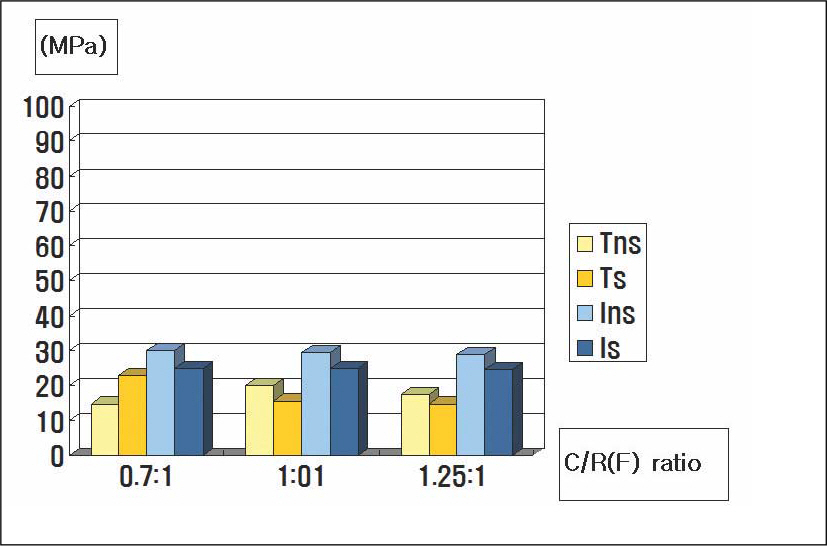
Fig. 6. Maximun von Mises stress under Load condition 1 (MPa); Tns: non-splinted tooth model, Ts: splinted tooth model, Ins: non-splinted implant model, Is: splinted implant model.

Fig. 7. Maximun von Mises stress under Load condition 2 (MPa); Tns: non-splinted tooth model, Ts: splinted tooth model, Ins: non-splinted implant model, Is: splinted implant model.

Fig. 8. Maximun von Mises stress under Load condition 3 (MPa); Tns: non-splinted tooth model, Ts: splinted tooth model, Ins: non-splinted implant model, Is: splinted implant model.
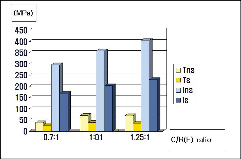
Fig. 9. Maximun von Mises stress under Load condition 4 (MPa); Tns: non-splinted tooth model, Ts: splinted tooth model, Ins: non-splinted implant model, Is: splinted implant model.

Fig. 10. Maximun von Mises stress under Load condition 5 (MPa); Tns: non-splinted tooth model, Ts: splinted tooth model, Ins: non-splinted implant model, Is: splinted implant model.
Reference
-
1.Bra � nemark PI., Breine U., Lindstrom J., Adell R., Hansson BO., Ohlsson A. Intra-osseous anchorage of dental prostheses. Ⅰ. Experimental studies. Scand J Plast Reconstr Surg. 1969. 3:81–100.2.Isidor F. Loss of osseointegration cause by occlusal load of oral implants. A clinical and radiographic study in monkeys. Clin Oral Implants Res. 1996. 7:143–52.3.Himmlova L., Dostalova T., Kacovsky A., Konvickova S. Influence of implant length and diameter on stress distribution: A finite element analysis. J Prosthet Dent. 2004. 91:20–5.4.Wiskott HW., Belser UC. Lack of integration of smooth titanium surfaces: A working hypothesis based on strains generated in the surrounding bone. Clin Oral Implants Res. 1999. 10:429–44.
Article5.Davarpanah M., Martinez H., Tecucianu JF. Apical-coronal implant position: recent surgical proposals technical note. Int J Oral Maxillofac Implants. 2000. 15:865–72.6.Yang HS., Lang LA., Felton DA. Finite element stress analysis on the effect of splinting in fixed partial dentures. J Prosthet Dent. 1999. 81:721–8.
Article7.Ishigaki S., Nakano T., Yamada S., Nakamura T., Takashima F. Biomechanical stress in bone surrounding an implant under simulated chewing. Clin Oral Implants Res. 2003. 14:97–102.
Article8.Eskitascioglu G., Usumez A., Sevimay M., Soykan E., Unsal E. The influence of occlusal loading location on stresses transferred to implant-supported prostheses and supporting bone: A three-dimensional finite element study. J Prosthet Dent. 2004. 91:144–50.
Article9.Ismail YH., Pahountis LN., Fleming JF. Comparison of two-dimensional and three-dimensional finite element analysis of a blade implant. Int J Oral Implantol. 1987. 4:25–31.10.Canay S., Hersek N., Akpinar I., As¸ik Z. Comparison of stress distribution around vertical and angled implants with finite-element analysis. Quintessence Int. 1996. 27:591–8.11.Timoshenko S., Young DH. Elements of strength of materials. 5th ed.Florence: Wadsworth;1968. p. 377–90.12.Papavasiliou G., Kamposiora P., Bayne SC., Felton DA. Three-dimensional finite element analysis of stress-distribution around single tooth implants as a function of bony support, prostheses type, and loading during function. J Prosthet Dent. 1996. 76:633–40.13.Penny RE., Kraal JH. Crown-to-root ratio: Its significance in restorative dentistry. J Prosthet Dent. 1979. 42:34–8.
Article14.Rosenstiel SF., land MF., Fujimoto J. Contemporary fixed prosthodontics. 1st ed.CV Mosby;1988. p. p48–50.15.Reynolds JM. Abutment selection for fixed prosthodontics. J Prosthet Dent. 1968. 19:483–8.
Article16.Dykema RW. Fixed partial prosthodontics. J Tenn Dent Assoc. 1962. 43:309–30.17.Chapman RJ. Principles of occlusion for implant prostheses: Guidelines for position, timing and force of occlusal contacts. Quintessence Int. 1989. 20:473–80.18.Ashman RB., Van Buskirk WC. The elastic properties of a human mandible. Adv Dent Res. 1987. 1:64–7.
Article19.Akpinar I., Anil N., Parnas L. A natural tooth' s stress distribution in occlusion with a dental implant. J Oral Rehabil. 2000. 27:538–45.20.Glickman I., Stein RS., Smulow JB. The effect of increased functional forces upon the periodontium of splinted and non-splinted teeth. J Periodontol. 1961. 32:290–9.
Article21.Glickman I., Roeber FW., Brion M., Pameijer JH. Photoelastic analysis of internal stresses in the periodontium created by occlusal forces. J Periodontol. 1970. 41:30–5.
Article22.Wang TM., Leu LJ., Wang J., Lin LD. Effect of prosthesis materials and prosthesis splinting on peri-implant bone stress around in poor quality bone: A numeric analysis. Int J Oral Maxillofac Implants. 2002. 17:231–7.23.Duyck J., Ro/nold HJ., Van Oosterwyck H., Naert I., Vander Sloten J., Ellingsen JE. The influence of static and dynamic loading on marginal bone reactions around osseointegrated implants: An animal experimental study. Clin Oral Implants Res. 2001. 12:207–18.
Article24.Hoshaw SJ., Brunski JB., Cochran GVB. Mechanical loading of Bra � nemark implants affects interfacial bone modeling and remodeling. Int J Oral Maxillofac Implants. 1994. 9:345–60.25.Ichikawa T., Kanitani H., Wigianto R., Kawamato N., Matsumato N. Influence of bone quality on the stress distribution. An in vitro experiment. Clin Oral Implants Res. 1997. 8:8–22.26.Meijer HJ., Starmans FJ., Steen WH., Bosman F. Loading conditions of endosseous implants in an edentulous human mandible: a three-dimensional, finite-element study. J Oral Rehabil. 1996. 23:757–63.
Article27.Barbier L., Vander SJ., Krzesinski G., Schepers E., Van der Perre G. Finite element analysis of non-axial versus axial loading of oral implants in the mandible of the dog. J Oral Rehabil. 1998. 25:847–58.
Article28.Choi MH., Kang JS., Boo SB., Oh SH., An OJ., Kang DW. Finite element stress analysis according to the point and surface occlusal loads on the implant prosthesis. J Kor Acad Stomatognethic & Occlusion. 2004. 20:83–94.29.Weinberg LA. Reduction of implant loading with therapeutic biomechanics. Implant Dent. 1998. 7:277–85.
Article30.Zhang JK., Chen ZQ. The study of effects of the elastic modulus of the materials substitute to human hard tissues on the mechanical state in the implant-bone interface by three-dimensional anisotropic finite element analysis. West China J Stomatol. 1998. 16:274–8.
- Full Text Links
-
- Actions
-
Cited
- CITED
-
- Close
- Share
-
- Similar articles
-
- Evaluation of the stress distribution in the external hexagon implant system with different hexagon height by FEM-3D
- Finite element analysis on maxillary molar implant under different C/R ratio
- Finite element stress analysis of implant prosthesis according to platform width of fixture
- A two-short-implant-supported molar restoration in atrophic posterior maxilla: A finite element analysis
- The non-linear FEM analysis of different connection lengths of internal connection abutment
