The non-linear FEM analysis of different connection lengths of internal connection abutment
- Affiliations
-
- 1Department of Prosthodontics, Post-Graduate Dental School, Yonsei University, Seoul, Republic of Korea. DONGHOOHAN@yuhs.ac
- 2Department of Mechanical Engineering, Yonsei University, Republic of Seoul, Korea.
- 3Department of Prosthodontics, Central Veterans Hospital, Seoul, Republic of Korea.
- KMID: 2162386
- DOI: http://doi.org/10.4047/jkap.2016.54.2.110
Abstract
- PURPOSE
This study is aimed to assess changes of stress distribution dependent on different connection lengths and placement of the fixture top relative to the ridge crest.
MATERIALS AND METHODS
The internal-conical connection implant which has a hexagonal anti-rotation index was used for FEM analysis on stress distribution in accordance with connection length of fixture-abutment. Different connection lengths of 2.5 mm, 3.5 mm, and 4.5 mm were designed respectively with the top of the fixture flush with residual ridge crest level, or 2 mm above. Therefore, a total of 6 models were made for the FEM analysis. The load was 170 N and 30-degree tilted.
RESULTS
In all cases, the maximum von Mises stress was located adjacent to the top portion of the fixture and ridge crest in the bone. The longer the connection length was, the lower the maximum von Mises stress was in the fixture, abutment, screw and bone. The reduction rate of the maximum von Mises stress depending on increased connection length was greater in the case of the fixture top at 2 mm above the ridge crest versus flush with the ridge crest.
CONCLUSION
It was found that the longer the connection length, the lower the maximum von Mises stress appears. Furthermore, it will help prevent mechanical or biological complications of implants.
Figure
-
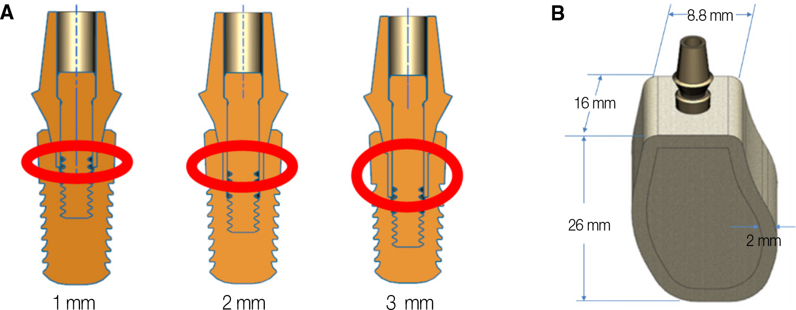
Fig. 1. (A) 1 mm, 2 mm, and 3 mm hexagonal index lengths and (B) geometry of CAD model.

Fig. 2. von Mises stress distribution in the fixtures of all models. (A) Model No. 1, (B) Model No. 2, (C) Model No. 3, (D) Model No. 4, (E) Model No. 5, (F) Model No. 6.
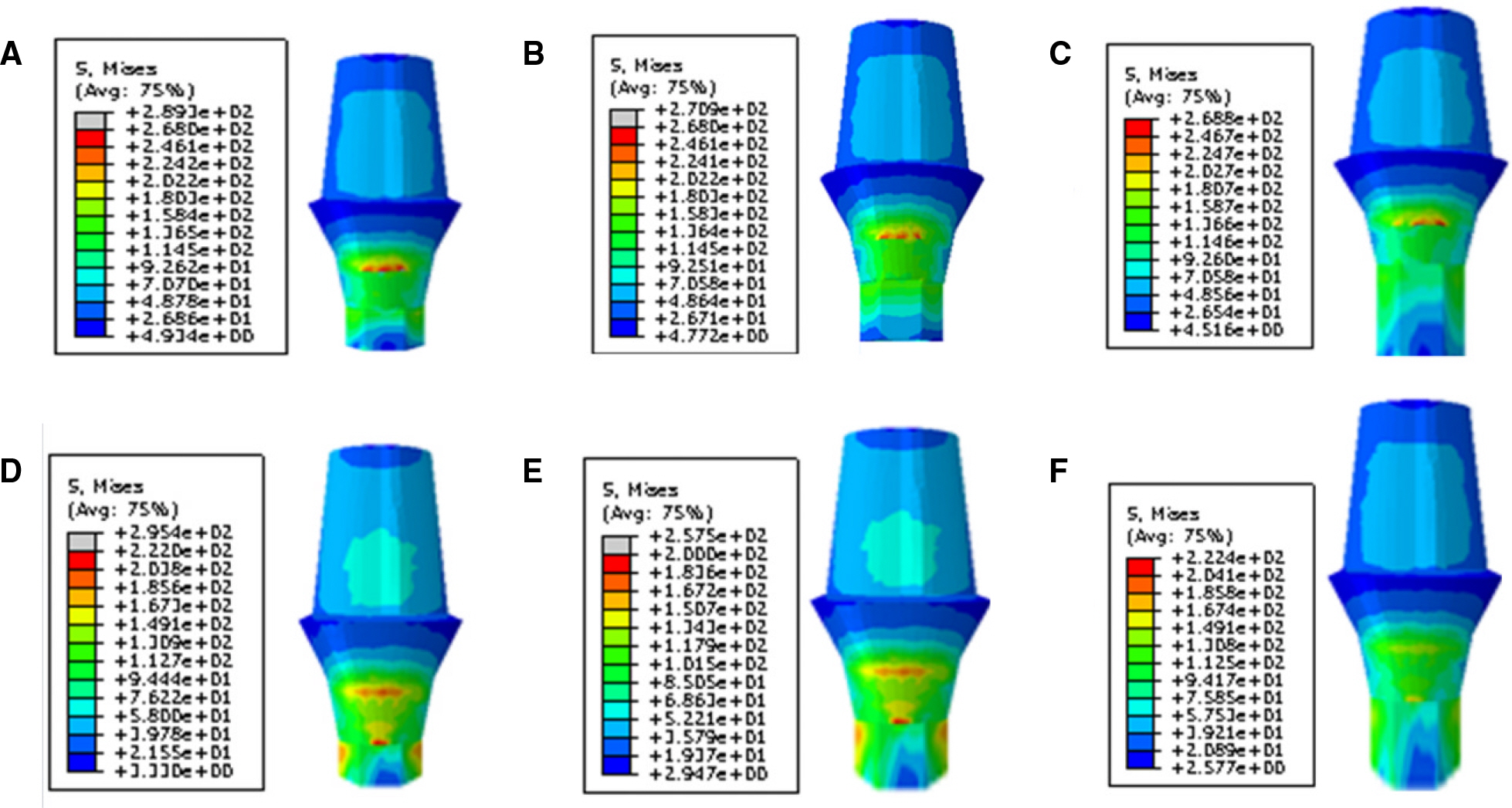
Fig. 3. von Mises stress distribution in the abutments of all models. (A) Model No. 1, (B) Model No. 2, (C) Model No. 3, (D) Model No. 4, (E) Model No. 5, (F) Model No. 6.

Fig. 4. von Mises stress distribution in the screws of all models. (A) Model No. 1, (B) Model No. 2, (C) Model No. 3, (D) Model No. 4, (E) Model No. 5, (F) Model No. 6.
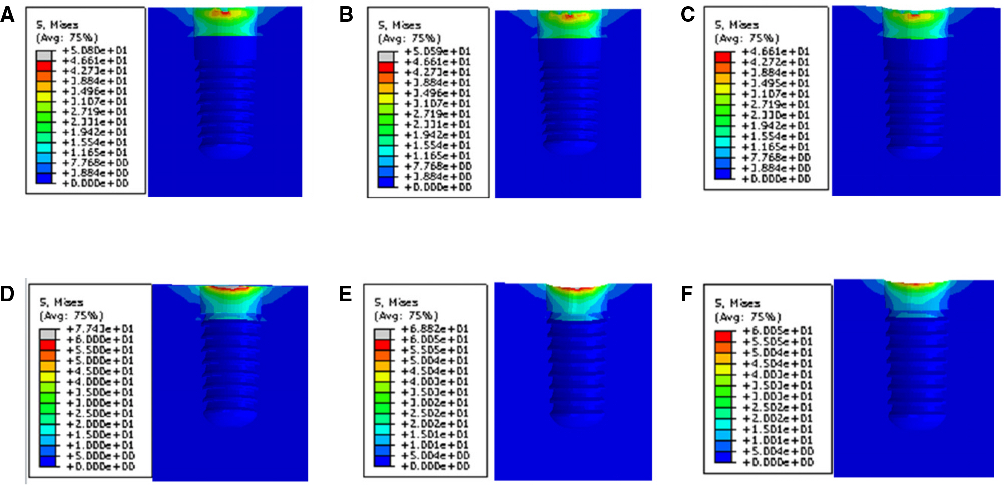
Fig. 5. von Mises stress distribution in the bones of all models. (A) Model No. 1, (B) Model No. 2, (C) Model No. 3, (D) Model No. 4, (E) Model No. 5, (F) Model No. 6.

Fig. 6. Bar graph of maximum von Mises stress of model No. 1, No. 2 and No. 3.
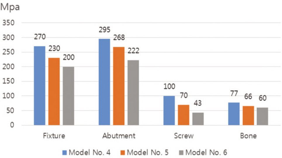
Fig. 7. Bar graph of maximum von Mises stress of model No. 4, No. 5 and No. 6.
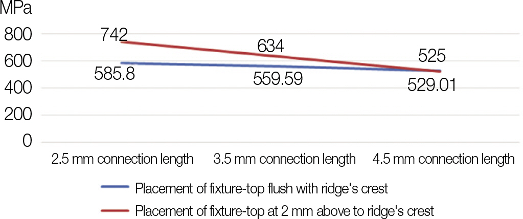
Fig. 8. Sum of maximum von Mises stresses of all components depending on connection lengths and fixture top level.
Reference
-
1.Simonis P., Dufour T., Tenenbaum H. Long-term implant survival and success: a 10-16-year follow-up of non-submerged dental implants. Clin Oral Implants Res. 2010. 21:772–7.
Article2.Wittneben JG., Buser D., Salvi GE., Bürgin W., Hicklin S., Brägger U. Complication and failure rates with implant-supported fixed dental prostheses and single crowns: a 10-year retrospective study. Clin Implant Dent Relat Res. 2014. 16:356–64.
Article3.Esposito M., Hirsch J., Lekholm U., Thomsen P. Differential diagnosis and treatment strategies for biologic complications and failing oral implants: a review of the literature. Int J Oral Maxillofac Implants. 1999. 14:473–90.4.Schwarz MS. Mechanical complications of dental implants. Clin Oral Implants Res. 2000. 11:156–8.
Article5.Segundo RM., Oshima HM., da Silva IN., Burnett LH Jr., Mota EG., Silva LL. Stress distribution of an internal connection implant prostheses set: a 3D finite element analysis. Stomatologija. 2009. 11:55–9.6.Tawil G. Peri-implant bone loss caused by occlusal overload: repair of the peri-implant defect following correction of the traumatic occlusion. A case report. Int J Oral Maxillofac Implants. 2008. 23:153–7.7.Naert I., Duyck J., Vandamme K. Occlusal overload and bone/implant loss. Clin Oral Implants Res. 2012. 23:95–107.
Article8.Mellal A., Wiskott HW., Botsis J., Scherrer SS., Belser UC. Stimulating effect of implant loading on surrounding bone. Comparison of three numerical models and validation by in vivo data. Clin Oral Implants Res. 2004. 15:239–48.9.Merz BR., Hunenbart S., Belser UC. Mechanics of the implant-abutment connection: an 8-degree taper compared to a butt joint connection. Int J Oral Maxillofac Implants. 2000. 15:519–26.10.Himmlova′ L., Dosta′lova′ T., Ka′covsky′ A., Konvickova′ S. Influence of implant length and diameter on stress distribution: a finite element analysis. J Prosthet Dent. 2004. 91:20–5.11.Hudieb MI., Wakabayashi N., Kasugai S. Magnitude and direction of mechanical stress at the osseointegrated interface of the microthread implant. J Periodontol. 2011. 82:1061–70.
Article12.Cehreli MC., Akça K., Iplikçioğlu H. Force transmission of one- and two-piece morse-taper oral implants: a nonlinear finite element analysis. Clin Oral Implants Res. 2004. 15:481–9.
Article13.Asvanund P., Morgano SM. Photoelastic stress analysis of external versus internal implant-abutment connections. J Prosthet Dent. 2011. 106:266–71.
Article14.Balik A., Karatas MO., Keskin H. Effects of different abutment connection designs on the stress distribution around five different implants: a 3-dimensional finite element analysis. J Oral Implantol. 2012. 38:491–6.
Article15.Schmitt CM., Nogueira-Filho G., Tenenbaum HC., Lai JY., Brito C., Döring H., Nonhoff J. Performance of conical abutment (Morse Taper) connection implants: a systematic review. J Biomed Mater Res A. 2014. 102:552–74.
Article16.Chu CM., Huang HL., Hsu JT., Fuh LJ. Influences of internal tapered abutment designs on bone stresses around a dental implant: three-dimensional finite element method with statistical evaluation. J Periodontol. 2012. 83:111–8.
Article17.Jung PW. Three dimensional finite element analysis on the contact between implant and abutment. Master's Thesis; Seoul;. Seoul National University;School of Dentistry. 2012.18.Kim JS. Influence of the length of internal connection on screw loosening in internal connection implants. Master's Thesis; Seoul; Department of Dentistry, Graduate School, Yonsei University;. 2010.19.Gultekin BA., Gultekin P., Yalcin S. Application of finite element analysis in implant dentistry. Finite Element Analysisd New Trends and Developments. Rijeka, Croatia: Intech;2012. p. 21–54.20.Kawaguchi T., Kawata T., Kuriyagawa T., Sasaki K. In vivo 3-dimensional measurement of the force exerted on a tooth during clenching. J Biomech. 2007. 40:244–51.
Article21.Balik A., Karatas MO., Keskin H. Effects of different abutment connection designs on the stress distribution around five different implants: a 3-dimensional finite element analysis. J Oral Implantol. 2012. 38:491–6.
Article22.Canullo L., Coelho PG., Bonfante EA. Mechanical testing of thin-walled zirconia abutments. J Appl Oral Sci. 2013. 21:20–4.
Article23.Nagasawa S., Hayano K., Niino T., Yamakura K., Yoshida T., Mizoguchi T., Terashima N., Tamura K., Ito M., Yagasaki H., Kubota O., Yoshimura M. Nonlinear stress analysis of titanium implants by finite element method. Dent Mater J. 2008. 27:633–9.
Article24.Sakaguchi RL., Borgersen SE. Nonlinear contact analysis of preload in dental implant screws. Int J Oral Maxillofac Implants. 1995. 10:295–302.25.Binon PP. Evaluation of three slip fit hexagonal implants. Implant Dent. 1996. 5:235–48.
Article26.Mangano C., Mangano F., Piattelli A., Iezzi G., Mangano A., La Colla L. Prospective clinical evaluation of 1920 Morse taper connection implants: results after 4 years of functional loading. Clin Oral Implants Res. 2009. 20:254–61.
Article27.Dibart S., Warbington M., Su MF., Skobe Z. In vitro evaluation of the implant-abutment bacterial seal: the locking taper system. Int J Oral Maxillofac Implants. 2005. 20:732–7.28.Rack A., Rack T., Stiller M., Riesemeier H., Zabler S., Nelson K. In vitro synchrotron-based radiography of micro-gap formation at the implant-abutment interface of two-piece dental implants. J Synchrotron Radiat. 2010. 17:289–94.29.McCracken M. Dental implant materials: commercially pure titanium and titanium alloys. J Prosthodont. 1999. 8:40–3.
Article30.Gratton DG., Aquilino SA., Stanford CM. Micromotion and dynamic fatigue properties of the dental implant-abutment interface. J Prosthet Dent. 2001. 85:47–52.
Article31.Cha HS., Kim YS., Jeon JH., Lee JH. Cumulative survival rate and complication rates of single-tooth implant; focused on the coronal fracture of fixture in the internal connection implant. J Oral Rehabil. 2013. 40:595–602.
Article32.Holmes DC., Loftus JT. Influence of bone quality on stress distribution for endosseous implants. J Oral Implantol. 1997. 23:104–11.33.Woon HY., Choi YS., Cho IH. Effect of implant types and bone resorption on the fatigue life and fracture characteristics of dental implant. J Dent Rehab Appl Sci. 2010. 26:121–43.34.Gehrke SA., Souza Dos Santos Vianna M., Dedavid BA. Influence of bone insertion level of the implant on the fracture strength of different connection designs: an in vitro study. Clin Oral Investig. 2014. 18:715–20.
Article35.Balshi TJ. An analysis and management of fractured implants: a clinical report. Int J Oral Maxillofac Implants. 1996. 11:660–6.
- Full Text Links
-
- Actions
-
Cited
- CITED
-
- Close
- Share
-
- Similar articles
-
- Finite element stress analysis of implant prosthesis with internal connection between the implant and the abutment
- Effect of cyclic loading on axial displacement of abutment into implant with internal tapered connection: a pilot study
- Concept and application of implant connection systems: Part II. Placement and restoration of external connection implant and tissue level implant
- Screw loosening and changes in removal torque relative to abutment screw length in a dental implant with external abutment connection after oblique cyclic loading
- Finite element stress analysis of implant prosthesis according to connection types of implant-abutment
