Imaging Sci Dent.
2016 Jun;46(2):117-125. 10.5624/isd.2016.46.2.117.
Comparison of interradicular distances and cortical bone thickness in Thai patients with Class I and Class II skeletal patterns using cone-beam computed tomography
- Affiliations
-
- 1Dental Division of Lamphun Hospital, Lamphun, Thailand.
- 2Department of Orthodontics and Pediatric Dentistry, Faculty of Dentistry, Chiang Mai University, Chiang Mai, Thailand.
- 3Division of Oral and Maxillofacial Radiology, Faculty of Dentistry, Chiang Mai University, Chiang Mai, Thailand. ajanhom@gmail.com
- KMID: 2308875
- DOI: http://doi.org/10.5624/isd.2016.46.2.117
Abstract
- PURPOSE
This study evaluated and compared interradicular distances and cortical bone thickness in Thai patients with Class I and Class II skeletal patterns, using cone-beam computed tomography (CBCT).
MATERIALS AND METHODS
Pretreatment CBCT images of 24 Thai orthodontic patients with Class I and Class II skeletal patterns were included in the study. Three measurements were chosen for investigation: the mesiodistal distance between the roots, the width of the buccolingual alveolar process, and buccal cortical bone thickness. All distances were recorded at five different levels from the cementoenamel junction (CEJ). Descriptive statistical analysis and t-tests were performed, with the significance level for all tests set at p<0.05.
RESULTS
Patients with a Class II skeletal pattern showed significantly greater maxillary mesiodistal distances (between the first and second premolars) and widths of the buccolingual alveolar process (between the first and second molars) than Class I skeletal pattern patients at 10 mm above the CEJ. The maxillary buccal cortical bone thicknesses between the second premolar and first molar at 8 mm above the CEJ in Class II patients were likewise significantly greater than in Class I patients. Patients with a Class I skeletal pattern showed significantly wider mandibular buccolingual alveolar processes than did Class II patients (between the first and second molars) at 4, 6, and 8 mm below the CEJ.
CONCLUSION
In both the maxilla and mandible, the mesiodistal distances, the width of the buccolingual alveolar process, and buccal cortical bone thickness tended to increase from the CEJ to the apex in both Class I and Class II skeletal patterns.
MeSH Terms
Figure
-
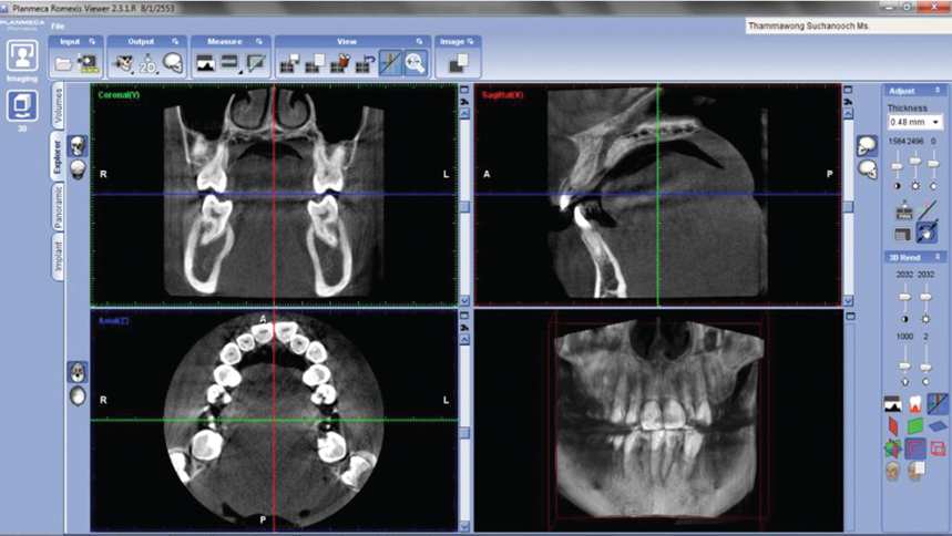
Fig. 1 A screen capture shows the Planmeca, Romexis Viewer 2.3.1.R.
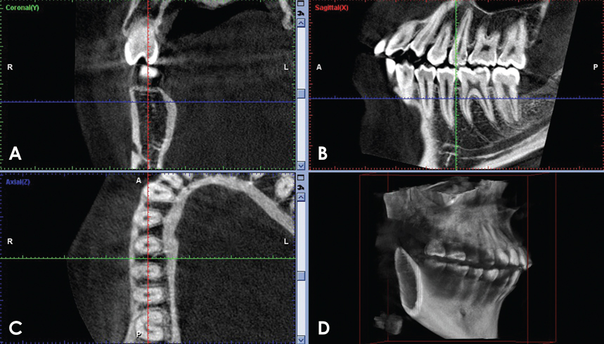
Fig. 2 A screen capture displays the possible orientations of a CBCT image of the interradicular area between the right mandibular first and second molars at a height of 4 mm from the CEJ. A. Coronal. B. Sagittal. C. Axial. D. Volume-rendering.
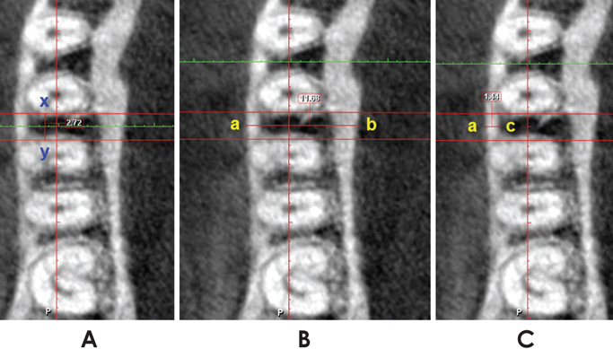
Fig. 3 Pictures show the measurements of the mesiodistal distance of the interradicular space (x-y) (A), the buccolingual alveolar process width (a-b) (B), and the buccal cortical bone thickness (a-c) (C).
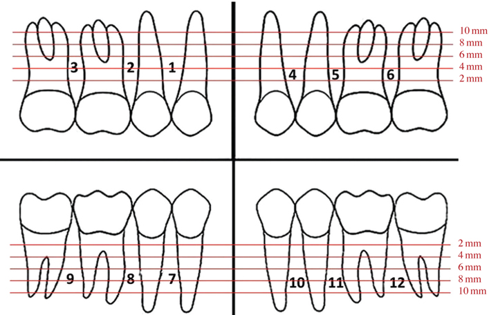
Fig. 4 A diagram shows the interradicular areas and different heights of measurement.
Reference
-
1. Baumgaertel S, Razavi MR, Hans MG. Mini-implant anchorage for the orthodontic practitioner. Am J Orthod Dentofacial Orthop. 2008; 133:621–627.
Article2. Wilmes B, Rademacher C, Olthoff G, Drescher D. Parameters affecting primary stability of orthodontic mini-implants. J Orofac Orthop. 2006; 67:162–174.
Article3. Chaimanee P, Suzuki B, Suzuki EY. "Safe zones" for miniscrew implant placement in different dentoskeletal patterns. Angle Orthod. 2011; 81:397–403.
Article4. Scarfe WC, Farman AG, Sukovic P. Clinical applications of cone-beam computed tomography in dental practice. J Can Dent Assoc. 2006; 72:75–80.
Article5. Kapila S, Conley RS, Harrell WE Jr. The current status of cone beam computed tomography imaging in orthodontics. Dentomaxillofac Radiol. 2011; 40:24–34.
Article6. Scarfe WC, Farman AG. What is cone-beam CT and how does it work? Dent Clin North Am. 2008; 52:707–730.
Article7. Poggio PM, Incorvati C, Velo S, Carano A. "Safe zones": a guide for miniscrew positioning in the maxillary and mandibular arch. Angle Orthod. 2006; 76:191–197.
Article8. Park J, Cho HJ. Three-dimensional evaluation of interradicular spaces and cortical bone thickness for the placement and initial stability of microimplants in adults. Am J Orthod Dentofacial Orthop. 2009; 136:314 e1–314 e12.
Article9. Fayed MM, Pazera P, Katsaros C. Optimal sites for orthodontic mini-implant placement assessed by cone beam computed tomography. Angle Orthod. 2010; 80:939–951.10. Monnerat C, Restle L, Mucha JN. Tomographic mapping of mandibular interradicular spaces for placement of orthodontic mini-implants. Am J Orthod Dentofacial Orthop. 2009; 135:428.e1–428.e9.11. Baumgaertel S, Hans MG. Buccal cortical bone thickness for mini-implant placement. Am J Orthod Dentofacial Orthop. 2009; 136:230–235.
Article12. Sawada K, Nakahara K, Matsunaga S, Abe S, Ide Y. Evaluation of cortical bone thickness and root proximity at maxillary interradicular sites for mini-implant placement. Clin Oral Implants Res. 2013; 24:Suppl A100. 1–7.
Article13. Schnelle MA, Beck FM, Jaynes RM, Huja SS. A radiographic evaluation of the availability of bone for placement of miniscrews. Angle Orthod. 2004; 74:832–837.
Article14. Hu KS, Kang MK, Kim TW, Kim KH, Kim HJ. Relationships between dental roots and surrounding tissues for orthodontic miniscrew installation. Angle Orthod. 2009; 79:37–45.
Article15. Motoyoshi M. Clinical indices for orthodontic mini-implants. J Oral Sci. 2011; 53:407–412.
Article16. Ludlow JB, Ivanovic M. Comparative dosimetry of dental CBCT devices and 64-slice CT for oral and maxillofacial radiology. Oral Surg Oral Med Oral Pathol Oral Radiol Endod. 2008; 106:106–114.
Article
- Full Text Links
-
- Actions
-
Cited
- CITED
-
- Close
- Share
-
- Similar articles
-
- Quantitative evaluation of palatal bone thickness in patients with normal and open vertical skeletal configurations using cone-beam computed tomography
- Location and shape of the mandibular lingula: Comparison of skeletal class I and class III patients using panoramic radiography and cone-beam computed tomography
- Maxillo-mandibular Transverse Relationship of Primary Second Molar and Permanent First Molar of Children in Mixed Dentition: A Cone-Beam Computed Tomography Analysis
- Assessment of lower incisor alveolar bone width using cone-beam computed tomography images in skeletal Class III adults of different vertical patterns
- Alveolar bone thickness and lower incisor position in skeletal Class I and Class II malocclusions assessed with cone-beam computed tomography
