Musculoskeletal intervention
- Affiliations
-
- 1Department of Radiology and Center for Imaging Science, Samsung Medical Center, Sungkyunkwan University School of Medicine, Seoul, Korea. jwjwkwon@gmail.com
- 2Department of Medical Device Management & Research, SAIHST, Sungkyunkwan University, Seoul, Korea.
- KMID: 2137557
- DOI: http://doi.org/10.5124/jkma.2015.58.6.502
Abstract
- Musculoskeletal intervention has significantly evolved over the last decade. A major reason for recent advancements could be attributed to the widespread use of image-guided techniques utilizing computed tomography, fluoroscopy, and ultrasonography. This change improved the approach of needles to the areas of pathology and decreased complication rates. This article reviews basic principles of the common image-guided diagnostic and therapeutic techniques as they relate to patients with musculoskeletal disease.
MeSH Terms
Figure
-
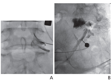
Figure 1 Lumbar transforaminal epidural steroid injection. (A) Anteroposterior radiograph of the lumbar spine following transforaminal epidural contrast injection. Contrast extends along with right L5 nerve root. (B) Intraepineural contrast injection. Right posterior oblique radiograph of the lumbosacral spine shows the tubular outline of the nerve root. Centrally, a feathery appearance is noted.
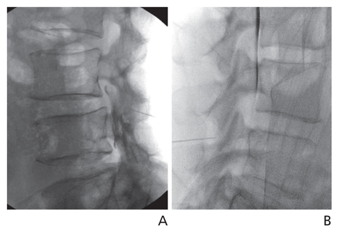
Figure 2 Lumbar interlaminar epidural steroid injection. (A) Lateral radiograph after contrast injection shows needle tip crossing the posterior edge of the facet joint and contrast dispersion in the posterior epidural space. (B) Dural puncture. Contrast layering on the ventral margin of the thecal sac showing entry of the needle into the thecal sac. The procedure should be terminated at this level.
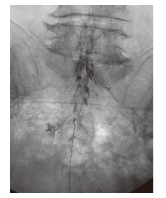
Figure 3 Caudal epidural steroid injection. Anteroposterior epidurogram shows typical "Christmas tree" pattern of epidural contrast in the lumbosacral canal.

Figure 4 Cervical transforaminal epidural steroid injection. (A) Supine oblique fluoroscopic image demonstrates an open foramen. The needle tip is positioned toward the posterior inferior aspect of the C6-7 neural foramen. (B) Anteroposterior fluoroscopic image immediately following contrast injection shows the needle tip located just beyond the lateral articular processes and contrast outlining the selected nerve root.
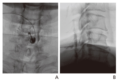
Figure 5 Cervical interlaminar epidural steroid injection. Anteroposterior (A) and lateral (B) epidurograms show contrast dispersion in the posterior epidural space.
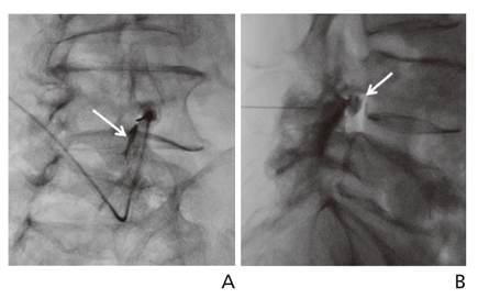
Figure 6 Lumbar facet joint injection (A) Oblique fluoroscopic image shows the needle tip and contrast (arrow) in the facet joint. (B) Lateral facet joint arthrogram shows contrast filling a facet joint synovial cyst (arrow).

Figure 7 Cervical facet joint injection. Anteroposterior (A) and lateral (B) arthrograms with the needle tip in right C3-4 facet joint show contrast within the joint capsule.
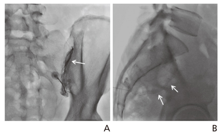
Figure 8 Sacroiliac joint injection. Anteroposterior (A) and lateral (B) radiograph with the needle tip in the right sacroiliac joint shows contrast outlining the sacroiliac joint cavity (arrows).
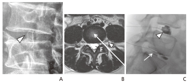
Figure 9 Lumbar discography. Oblique radiograph (A) shows target site for oblique posterolateral approach, just anterior to facet joint (arrowhead). Axial T2-weighted magnetic resonance image (B) at level of lumbar disc shows oblique posterolateral approach (long arrow). Arrowhead indicates exiting spinal nerve. (C) Lateral fluoroscopic image. Injection of the L5-S1 disc (arrow) with 0.5 mL of contrast material reproduced the patient's concordant pain. Note the L4-5 discogram (arrowhead) showing cotton ball appearance without any pain provocation. F, facet joint.

Figure 10 Cervical discography technique. The skin entrance is along the anterior border of the sternocleidomastoid muscle. The discographer's fingers manually displace the vascular structures. The needle is advanced ventral to the finger (From Kwon JW, et al. J Korean Radiol Soc 2006;55:103-110, according to the Creative Commons license) [12].
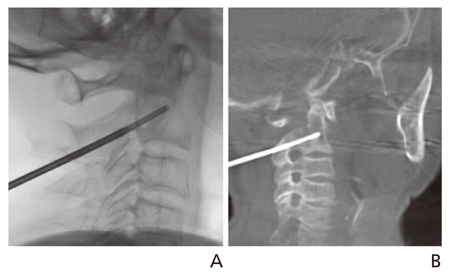
Figure 11 Fluoroscopic-guided C2 biopsy. (A) Lateral fluoroscopic image shows biopsy needle located in the C2 vertebra. (B) Cone-beam computed tomography image shows the needle tip not over the anterior cortex of the vertebral body. The pathology revealed metastasis from lung cancer.
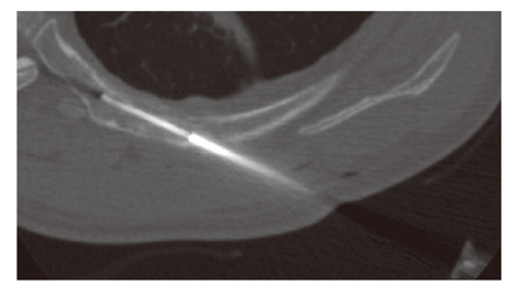
Figure 12 Computed tomography-guided biopsy for a rib metastasis from lung cancer in a 55-year-old man. Computed tomography scan during the biopsy shows the biopsy needle tip in the destructed rib with a route along the long axis of the rib.
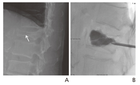
Figure 13 A 78-year-old woman with L1 vertebral compression fracture showing increased height of body after vertebroplasty (A) Lateral radiograph shows compression fracture with horizontal vacuum cleft (arrow) in the L1 vertebral body. (B) Lateral radiograph after polymethyl methacrylate injection shows injected material has entered vacuum cleft. Note increase in height of compressed vertebral body.
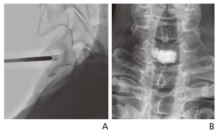
Figure 14 Cervical vertebroplasty for C7 metastasis from thyroid cancer. (A) Lateral fluoroscopic image shows the vertebroplasty needle placed into the seventh vertebral body using the anterolateral approach. (B) Anteroposterior radiograph after vertebroplasty shows bone cement depositing well within the vertebral body without any leakage.
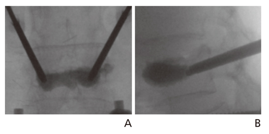
Figure 15 Kyphoplasty. Anteroposterior (A) and lateral (B) fluoroscopic images show cement instillation filling the previously created void.
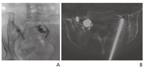
Figure 16 Sacroplasty for sacral insufficiency fracture of an 84-year-old woman. (A) Under fluoroscopy guidance, a needle was placed at the left sacral ala along the short axis of the sacrum parallel to the sacroiliac joint. The right sacral ala is filled with the cement. (B) After the needle placement using fluoroscopy, the patient underwent cone-beam computed tomography. The cone-beam computed tomography image shows the needle placed within the left sacrum ala, not over the anterior cortex of the sacrum.
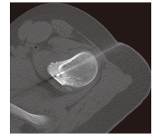
Figure 17 Computed tomography-guided radiofrequency thermal ablation of osteoid osteoma in left proximal femur of 13-year-old man. Computed tomography scan during the procedure shows radiofrequency electrode tip in nidus.
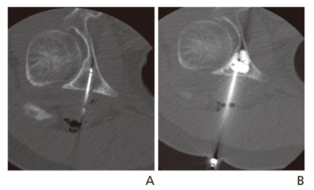
Figure 18 Pain palliation and stabilization of extraskeletal chondrosarcoma metastatic lesion, involving the periacetabular region, using RF ablation followed by cementoplasty. (A) Non-contrast computed tomography of the pelvis shows a RF probe placed into an osteolytic lesion in the right retroacetabular region. (B) Non-contrast computed tomography immediately following cement injection shows polymethyl methacrylate cement filling the retro-acetabular defect.
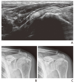
Figure 19 Percutaneous aspiration for Calcific Tendinitis. (A) A longitudinal scan of the supraspinatus tendon shows well defined calcium deposits that were punctured by a fine needle with ultrasonographic guidance. (B) Plain radiography showing amorphous calcific opacity in the left shoulder area. (C) Follow-up plain radiography after percutaneous puncture and aspiration shows the almost complete disappearance of the calcific opacity in the left shoulder area.
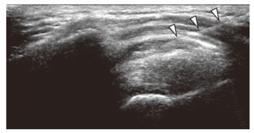
Figure 20 Subacromial Steroid Injection. A fine needle (arrowheads) was introduced into the subacromial bursa with ultrasonographic guidance.
Cited by 1 articles
-
Recent trends in radiology
Eun-Young Kang
J Korean Med Assoc. 2015;58(6):499-501. doi: 10.5124/jkma.2015.58.6.499.
Reference
-
1. Lee JW, Kim SH. Epidural steroid injection. Neurointervention. 2008; 3:20–27.2. White AH, Derby R, Wynne G. Epidural injections for the diagnosis and treatment of low-back pain. Spine (Phila Pa 1976). 1980; 5:78–86.
Article3. Hession WG, Stanczak JD, Davis KW, Choi JJ. Epidural steroid injections. Semin Roentgenol. 2004; 39:7–23.
Article4. Abbasi A, Malhotra G, Malanga G, Elovic EP, Kahn S. Complications of interlaminar cervical epidural steroid injections: a review of the literature. Spine (Phila Pa 1976). 2007; 32:2144–2151.5. Pfirrmann CW, Oberholzer PA, Zanetti M, Boos N, Trudell DJ, Resnick D, Hodler J. Selective nerve root blocks for the treatment of sciatica: evaluation of injection site and effectiveness: a study with patients and cadavers. Radiology. 2001; 221:704–711.
Article6. Choi SJ, Ahn JH, Kim C, Song JS, Jung SM, Ryu DS, Park MS, Lee JH. Cervical transforaminal epidural steroid injection (TFESI): role of MR imaging and epidurography. J Korean Soc Radiol. 2011; 64:25–32.
Article7. Lee JW, Park KW, Chung SK, Yeom JS, Kim KJ, Kim HJ, Kang HS. Cervical transforaminal epidural steroid injection for the management of cervical radiculopathy: a comparative study of particulate versus non-particulate steroids. Skeletal Radiol. 2009; 38:1077–1082.
Article8. Kwon JW, Lee JW, Kim SH, Choi JY, Yeom JS, Kim HJ, Kwack KS, Moon SG, Jun WS, Kang HS. Cervical interlaminar epidural steroid injection for neck pain and cervical radiculopathy: effect and prognostic factors. Skeletal Radiol. 2007; 36:431–436.
Article9. Tuite MJ. Facet joint and sacroiliac joint injection. Semin Roentgenol. 2004; 39:37–51.
Article10. Lindblom K. Diagnostic puncture of intervertebral disks in sciatica. Acta Orthop Scand. 1948; 17:231–239.
Article11. Anderson MW. Lumbar discography: an update. Semin Roentgenol. 2004; 39:52–67.
Article12. Kwon JW, Kim SH, Lee JW, Kwack KS, Choi JY, Yeom JS, Kim HJ, Kim KJ, Chung SK, Kim C, Moon SG, Jun WS, Kang HS. Value of preoperative cervical discography. J Korean Radiol Soc. 2006; 55:103–110.
Article13. Gogna A, Peh WC, Munk PL. Image-guided musculoskeletal biopsy. Radiol Clin North Am. 2008; 46:455–473.
Article14. Hwang CM, Shin MJ, Kim SM, Lee SH, Lee SM, Shin JH, Kwon ST, Bae SJ. The diagnostic usefulness of CT-guided needle biopsy or aspiration in infectious spondylitis. J Korean Radiol Soc. 2003; 48:497–504.
Article15. Kim S, Park HJ, Lee SY, Chung EC, Park HW, Kook SH, Rho MH. Initial experience with percutaneous needle aspiration of paraspinal lesions using xperguide cone-beam CT. J Korean Soc Radiol. 2013; 68:245–250.
Article16. Galibert P, Deramond H, Rosat P, Le Gars D. Preliminary note on the treatment of vertebral angioma by percutaneous acrylic vertebroplasty. Neurochirurgie. 1987; 33:166–168.17. Kim YJ, Lee JW, Kim KJ, Chung SK, Kim HJ, Park JM, Kang HS. Percutaneous vertebroplasty for intravertebral cleft: analysis of therapeutic effects and outcome predictors. Skeletal Radiol. 2010; 39:757–766.
Article18. Peh WC, Munk PL, Rashid F, Gilula LA. Percutaneous vertebral augmentation: vertebroplasty, kyphoplasty and skyphoplasty. Radiol Clin North Am. 2008; 46:611–635.
Article19. Lee MH, Ahn JM, Chung HW, Lim HK, Suh JG, Kwag HJ, Hong HP, Kim BM. Osteoid osteoma treated with percutaneous radiofrequency ablation: MR imaging follow-up. Eur J Radiol. 2007; 64:309–314.
Article20. Kang SE, Lee JW, Kim JH, Park KW, Yeom JS, Kang HS. Percutaneous sacroplasty with the use of C-arm flat-panel detector CT: technical feasibility and clinical outcome. Skeletal Radiol. 2011; 40:453–460.
Article21. Choi J, Raghavan M. Diagnostic imaging and image-guided therapy of skeletal metastases. Cancer Control. 2012; 19:102–112.
Article22. Yoon YC. Ultrasonography of the rotator cuff. J Korean Soc Ultrasound Med. 2006; 25:109–125.23. Lee MH. Steroid injection for painful shoulder: usefulness of ultrasound-guided approach. J Korean Soc Med Ultrasound. 2004; 23:41–45.
- Full Text Links
-
- Actions
-
Cited
- CITED
-
- Close
- Share
-
- Similar articles
-
- Characteristics of Work-Related Musculoskeletal Disorders and Effect of Intervention Program in Shipyard Workers
- Ultrasound-guided Intervention in Musculoskeletal System
- Introduction to Knobology Focusing on B Mode and Doppler Setting in Musculoskeletal Ultrasound
- Utilization of Musculoskeletal Ultrasound
- Ultrasonography-Guided Common Musculoskeletal Interventions from Head to Toe: Procedural Tips for General Radiologists
