J Korean Orthop Assoc.  2015 Apr;50(2):93-106. 10.4055/jkoa.2015.50.2.93.

Ultrasound-Guided Intervention in Thoracic Spine

Affiliations
  • 1Department of Orthopedic Surgery, Seoul Sacred Heart General Hospital, Seoul, Korea. msh124@paran.com

Abstract

Even though thoracic spinal pain may be less common than low back and neck pain, the prevalence of thoracic pain in the general population is 13% to 15% in the literature and it can be as disabling as lumbar or cervical pain. Although thoracic interventions have been reported to be effective, it is rarely performed due to concerns of creating iatrogenic pneumothorax. Fluoroscopy-guided interventions are more accurate procedures than blind technique but still cannot prevent pneumothorax. In recent reports in the literature, use of ultrasound-guided interventions minimized the risk of pneumothorax and vascular puncture because ultrasound can visualize lung with pleura and also detect vascular structures by Doppler scan. Compared with fluoroscopy, ultrasound imaging has no known contraindications, produces no ionizing radiation, enables direct visualization of neurovascular and soft tissue structures, and provides real-time visualization of needle passage toward the intended target. We therefore conducted a review to investigate the feasibility of performing thoracic interventions under real-time ultrasound guidance.

Keyword

thoracic spine; ultrasound; intervention

MeSH Terms

Fluoroscopy
Lung
Neck Pain
Needles
Pleura
Pneumothorax
Prevalence
Punctures
Radiation, Ionizing
Spine*
Ultrasonography

Figure

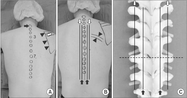
  • Figure 1 (A) Surface anatomy of the posterior thoracic region. It is customary to count thoracic spinous processes (circular markings on the midline) from the prominence caused by the seventh cervical spinous process (black arrow) as a top. Usually the first thoracic is more prominent than the seventh cervical. The root of the spine of the scapula (white arrow) is on a level with the tip of the spinous process of the third thoracic vertebra (3), and the inferior angle with that of the seventh (7). Medial border of scapular (arrowheads) is located from the second thoracic to the seventh. (B) Drawing the line one finger breadth laterally from the midline, there are laminae and facet joints alternatively on this line (black arrows). Two finger breadths laterally, transverse processes are on this line (white arrows). The upper and lower margins of the rib can be palpated in the lateral aspect from the transverse process area (arrowheads). (C) Same lines as (B) on the artificial thoracic spine model. Dotted line explains that the spinous processes of thoracic vertebrae project posteriorly at an extreme inferior angle, such that the inferior border of the spinous process overlies the lamina and the transverse process of the vertebra below.

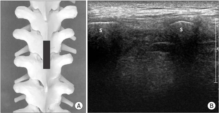
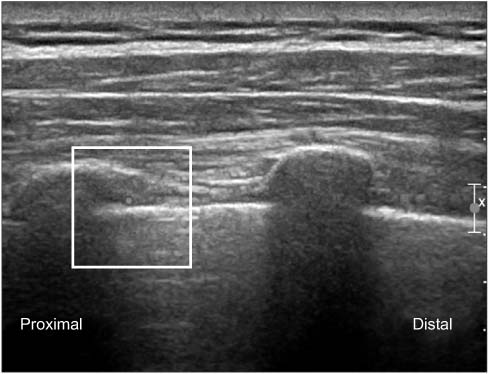
  • Figure 2 (A) Position of the probe (black bar) for (B) on the artificial spine model. (B) Ultrasonography on longitudinal scan at midline of the posterior thoracic area shows spinous processes (S) superficially.

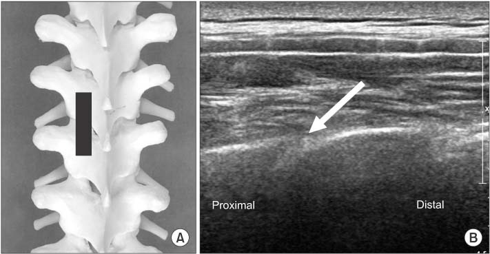
  • Figure 3 (A) Position of the probe (black bar) for (B) on the artificial spine model. (B) After the probe is slightly moved laterally over the lamina, between two hyperechoic lines which represent the inferior and superior articular processes, the thoracic facet joint (arrow) can be visualized in the paramedian sagittal image.

  • Figure 4 (A) Position of the probe (black bar) for (B) on the artificial spine model. (B) Probe is initially placed at a point 2 finger breadths lateral to the tip of the spinous process in a longitudinal orientation, obtaining a sagittal paramedian view of the transverse process (T), and underlying pleura (arrows). The pleura is deeper, 'shimmers' and moves with respiration.

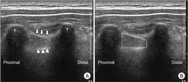
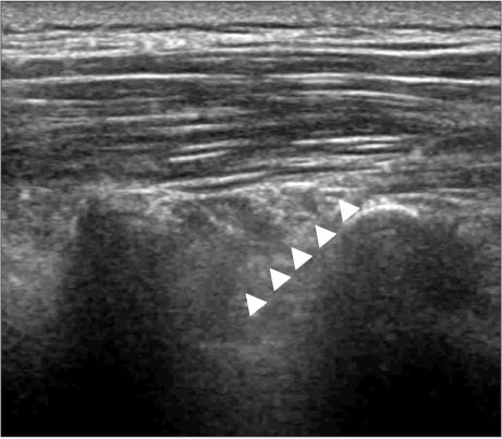
  • Figure 5 (A) At the sagittal paramedian view of the transverse process (T), superior costotransverse ligament (white arrows) and underlying pleura (arrowheads) can be visualized. Superior costotransverse ligament is seen as a collection of homogeneous linear echogenic bands alter-nating with echo poor areas running from 1 transverse process to the next. (B) Thoracic paravertebral space is the dotted area between superior costotransverse ligament and pleura.

  • Figure 6 (A) Position of the probe (black bar) for (B) on the artificial spine model. (B) Probe is placed more laterally on the rib in a longitudinal orientation, obtaining a sagittal paramedian view of the rib which has a rounder appearance than the transverse process (R), and underlying pleura (arrowheads).

  • Figure 7 Doppler scan shows the intercostal artery which runs inferior and deep aspect of rib.

  • Figure 8 (A) Position of the probe (black bar) for (B) on the artificial spine model. (B) Transverse scan at the midline shows the spinous process (S), lamina (L) and transverse process (T) using a linear probe. (C) Using a curved probe, a wider image can be achieved. Pleura (arrows) can be seen at the lateral side of the transverse process.

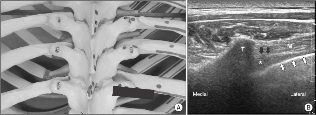
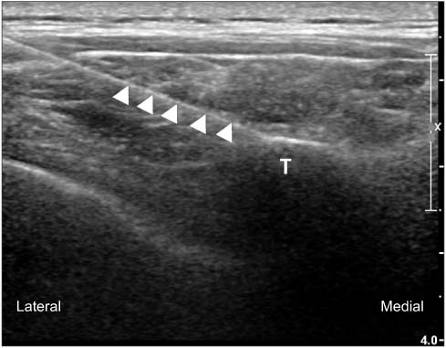
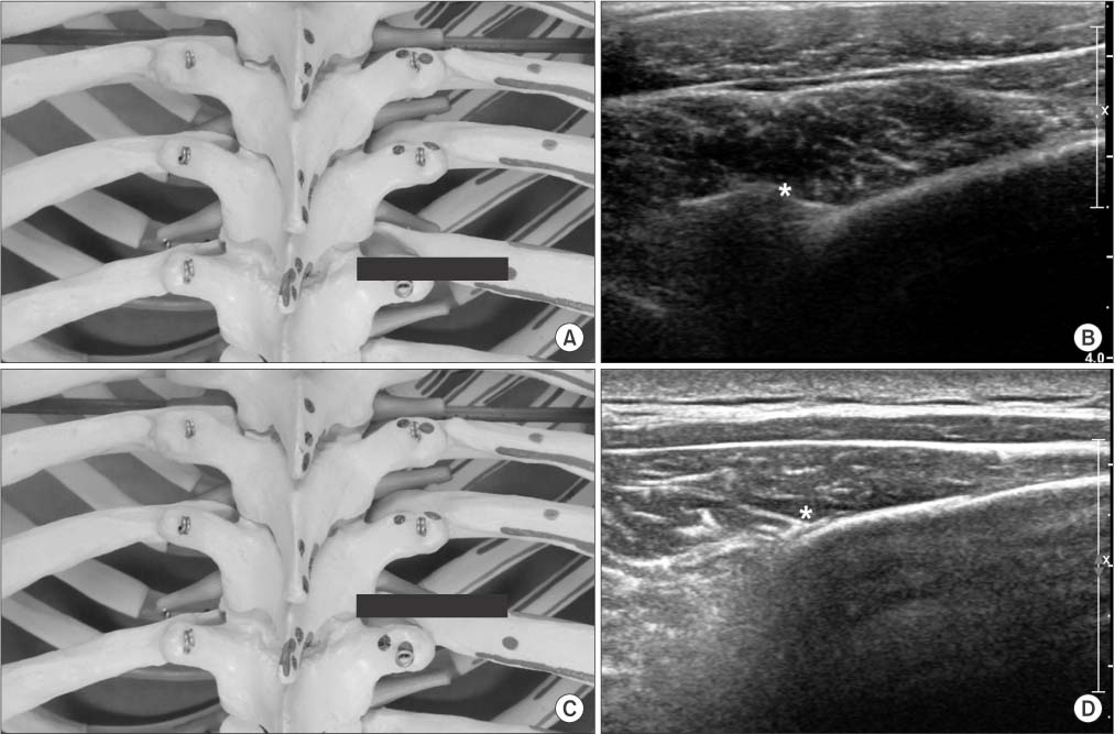
  • Figure 9 (A) Position of the probe (black bar) for (B) on the artificial spine model. (B) The probe is moved laterally from the midline in a transverse to the vertebral column and a partial oblique position parallel to the rib (transverse paramedian scan). Hereafter, the transverse process (T) is located in the middle of the image, and laterally indicated by visualization of the shimmering parietal pleura (white arrows) which dips medially and intercostal muscle (M) superficially. Superior costotransverse ligament (black arrows) is generally seen as a thin radio-opaque line extending from the transverse process, creating a wedge shaped pocket which represents the thoracic paravertebral space (asterisk).

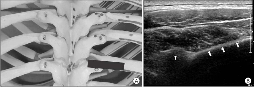
  • Figure 10 (A) Position of the probe (black bar) for (B) on the artificial spine model. (B) The probe is moved cranially until rib view can be obtained. The rib (arrows) is more superficial than pleura with posterior acoustic shadow seen beneath it and replacing intercostal muscle area of Fig. 9B. T, transverse process.

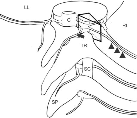
  • Figure 11 Schematic representation of thoracic paravertebral space (TPVS). TPVS is a triangular column (black lined triangular column) bounded posteriorly by the transverse process and the superior costotransverse ligament (SC) which travel between two adjacent transverse processes and ribs. The medial boundary is the vertebral column and foramen. The anterior boundary is the parietal pleura. Laterally, TPVS tapers as it communicates with the intercostal space. The contents of the thoracic paravertebral space include the intercostal nerve (arrowheads), the dorsal and ventral rami, the rami communicantes (white arrow) to the sympathetic chain. medial branch (black arrow) from dorsal rami. C, spinal cord; LL, left lung; RL, right lung; TR, transverse process and rib; SP, spinous process.

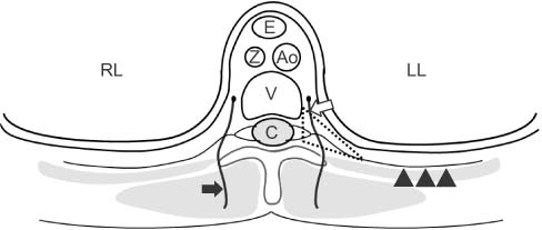
  • Figure 12 Schematic representation of thoracic paravertebral space (TPVS) (dotted area) in a transverse plane. In TPVS, there are the intercostal nerve (arrowheads), the dorsal and ventral rami, the rami communicantes (white arrow) to the sympathetic chain, medial branch (black arrow) from dorsal rami. LL, left lung; RL, right lung; E, esophagus; Z, azygos vein; Ao, aorta; V, vertebral body; C, spinal cord.

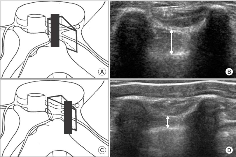
  • Figure 13 (A, B) Because thoracic paravertebral space (TPVS) tapers laterally, TPVS may have larger anterior-posterior dimension (arrow) if the probe is placed medially. (C, D) TPVS may have less anterior-posterior dimension (arrow) if the probe is placed too far laterally.

  • Figure 14 The midpoint of the transducer is aligned midway between the 2 adjacent transverse processes in a longitudinal scan, and a needle is introduced in an in-plane approach in a cephalad orientation. The paravertebral space is entered between the 2 transverse processes avoiding bony contact. The needle (arrowheads) is advanced under direct vision to puncture the costotransverse ligament and until the needle tip is located immediately above the pleura. During the injection of local anesthetic, the pleural depression by the injectant material should be confirmed by ultrasound.

  • Figure 15 The midpoint of the transducer is aligned midway between the 2 adjacent ribs in a longitudinal scan, and a needle introduced in an in-plane approach in a cephalad orientation. The needle (arrowheads) is advanced to the area of the intercostal vessel which has already been confirmed by Doppler scan. During injection of the local anesthetic, the pleural depression by the injectant material should be confirmed by ultrasound.

  • Figure 16 (A) Schematic representation of the medial branch at the upper thoracic levels (T1-T4) and lower levels (T9-T10). Medial branch contacts at the superolateral corner of the transverse process (arrow). (B) At mid-thoracic levels (T5-T8), the medial branch does not contact with bone and is suspended in the intertransverse space (arrow). (C) The T11-T12 medial branches have a course analogous to that of the lumbar medial branches, crossing the base of the transverse process (arrow).

  • Figure 17 Needle (arrowheads) is introduced for medial branch block by use of real-time in-plane ultrasound guidance to the target point, which is the superolateral corner of the transverse process (T) at the transverse paramedian scan.

  • Figure 18 (A) Position of the probe (black bar) for (B) on the artificial spine model. (B) At T5-T8 levels, medial branch passes dorsally and caudally in the intertransverse space just above to the typical target point on the superolateral corner of the transverse process. Asterisk indicates the most cranial point of the superolateral corner of the transverse process. Laterally rib is shown. (C) Position of the probe (black bar) for (D) on the artificial spine model. (D) From the point of (B), the probe is moved cranially into the intertransverse space. Asterisks indicate the target point at the intertransverse space. The depth of the target point is the same as the depth of the transverse process of (B). The height of the injection is opposite the upper border of the rib at the target level. After the needle strikes the rib, it will be withdrawn until its tip is at the same height from the skin as that of the superolateral corner of the transverse process.

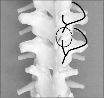
  • Figure 19 The medial branches (black lines) to a particular joint (dotted circle) are the ones that cross the transverse process above the joint and the transverse process below the joint. Numerically, if the joint to be blocked is the Ta-Ta+1 joint, the transverse processes required are the Ta and Ta+1 transverse processes. Respectively, these are crossed by the Ta-1 and Ta medial branches.


Cited by  1 articles

The Validation of Ultrasound-Guided Target Segment Identification in Thoracic Spine as Confirmed by Fluoroscopy
Ju-Yeong Heo, Ji-Won Lee, Cheol-Hwan Kim, Sang-Min Lee, Yong-Soo Choi
Clin Orthop Surg. 2017;9(4):472-479.    doi: 10.4055/cios.2017.9.4.472.


Reference

1. Linton SJ, Hellsing AL, Halldèn K. A population-based study of spinal pain among 35-45-year-old individuals. Prevalence, sick leave, and health care use. Spine (Phila Pa 1976). 1998; 23:1457–1463.
2. Leboeuf-Yde C, Nielsen J, Kyvik KO, Fejer R, Hartvigsen J. Pain in the lumbar, thoracic or cervical regions: do age and gender matter? A population-based study of 34,902 Danish twins 20-71 years of age. BMC Musculoskelet Disord. 2009; 10:39.
Article
3. Edmondston SJ, Singer KP. Thoracic spine: anatomical and biomechanical considerations for manual therapy. Man Ther. 1997; 2:132–143.
Article
4. Moon SH. Ultrasound-guided intervention in lumbar spine. J Korean Orthop US Soc. 2013; 2:81–93.
5. Moon SH. Ultrasound-guided intervention in cervical spine. J Korean Orthop US Soc. 2014; 1:49–66.
6. Purcell-Jones G, Pither CE, Justins DM. Paravertebral somatic nerve block: a clinical, radiographic, and computed tomographic study in chronic pain patients. Anesth Analg. 1989; 68:32–39.
7. Richardson J, Lönnqvist PA. Thoracic paravertebral block. Br J Anaesth. 1998; 81:230–238.
Article
8. Davies RG, Myles PS, Graham JM. A comparison of the analgesic efficacy and side-effects of paravertebral vs epidural blockade for thoracotomy: a systematic review and meta-analysis of randomized trials. Br J Anaesth. 2006; 96:418–426.
9. Joshi GP, Bonnet F, Shah R, et al. A systematic review of randomized trials evaluating regional techniques for postthoracotomy analgesia. Anesth Analg. 2008; 107:1026–1040.
Article
10. Eason MJ, Wyatt R. Paravertebral thoracic block-a reappraisal. Anaesthesia. 1979; 34:638–642.
Article
11. Lönnqvist PA, MacKenzie J, Soni AK, Conacher ID. Paravertebral blockade. Failure rate and complications. Anaesthesia. 1995; 50:813–815.
12. Cowie B, McGlade D, Ivanusic J, Barrington MJ. Ultrasound-guided thoracic paravertebral blockade: a cadaveric study. Anesth Analg. 2010; 110:1735–1739.
13. Renes SH, Bruhn J, Gielen MJ, Scheffer GJ, van Geffen GJ. In-plane ultrasound-guided thoracic paravertebral block: a preliminary report of 36 cases with radiologic confirmation of catheter position. Reg Anesth Pain Med. 2010; 35:212–216.
14. O Riain SC, Donnell BO, Cuffe T, Harmon DC, Fraher JP, Shorten G. Thoracic paravertebral block using real-time ultrasound guidance. Anesth Analg. 2010; 110:248–251.
15. Shanti CM, Carlin AM, Tyburski JG. Incidence of pneumothorax from intercostal nerve block for analgesia in rib fractures. J Trauma. 2001; 51:536–539.
Article
16. Ozkan D, Akkaya T, Karakoyunlu N, et al. Effect of ultrasound-guided intercostal nerve block on postoperative pain after percutaneous nephrolithotomy: prospective randomized controlled study. Anaesthesist. 2013; 62:988–994.
17. Manchikanti L, Boswell MV, Singh V, Pampati V, Damron KS, Beyer CD. Prevalence of facet joint pain in chronic spinal pain of cervical, thoracic, and lumbar regions. BMC Musculoskelet Disord. 2004; 5:15.
Article
18. Manchikanti L, Singh V, Pampati V, Beyer CD, Damron KS. Evaluation of the prevalence of facet joint pain in chronic thoracic pain. Pain Physician. 2002; 5:354–359.
Article
19. Manchikanti L, Singh V, Falco FJ, Cash KA, Pampati V, Fellows B. Comparative effectiveness of a one-year follow-up of thoracic medial branch blocks in management of chronic thoracic pain: a randomized, double-blind active controlled trial. Pain Physician. 2010; 13:535–548.
20. Dreyfuss P, Tibiletti C, Dreyer SJ. Thoracic zygapophyseal joint pain patterns. A study in normal volunteers. Spine (Phila Pa 1976). 1994; 19:807–811.
21. Fukui S, Ohseto K, Shiotani M. Patterns of pain induced by distending the thoracic zygapophyseal joints. Reg Anesth. 1997; 22:332–336.
Article
22. Atluri S, Datta S, Falco FJ, Lee M. Systematic review of diagnostic utility and therapeutic effectiveness of thoracic facet joint interventions. Pain Physician. 2008; 11:611–629.
23. Chua WH, Bogduk N. The surgical anatomy of thoracic facet denervation. Acta Neurochir (Wien). 1995; 136:140–144.
Article
24. Manchikanti L, Manchikanti KN, Manchukonda R, Pampati V, Cash KA. Evaluation of therapeutic thoracic medial branch block effectiveness in chronic thoracic pain: a prospective outcome study with minimum 1-year follow up. Pain Physician. 2006; 9:97–105.
25. Stulc SM, Hurdle MF, Pingree MJ, Brault JS, Porter CA. Ultrasound-guided thoracic facet injections: description of a technique. J Ultrasound Med. 2011; 30:357–362.
Full Text Links
  • JKOA
Actions
Cited
CITED
export Copy
Close
Share
  • Twitter
  • Facebook
Similar articles
Copyright © 2024 by Korean Association of Medical Journal Editors. All rights reserved.     E-mail: koreamed@kamje.or.kr