Multislice CT Angiography of Fenestrated Endovascular Stent Grafting for Treating Abdominal Aortic Aneurysms: a Pictorial Review of the 2D/3D Visualizations
- Affiliations
-
- 1Discipline of Medical Imaging, Department of Imaging and Applied Physics, Curtin University of Technology, Perth, Western Australia, Australia. z.sun@curtin.edu.au
- 2Department of Vascular Surgery, Royal Perth Hospital, School of Medicine and Pathology, University of Western Australia, Western Australia, Australia.
- 3Cook R & D, Perth, Western Australia, Australia.
- 4School of Public Health, Curtin University of Technology, Perth, Western Australia, Australia.
- KMID: 1779456
- DOI: http://doi.org/10.3348/kjr.2009.10.3.285
Abstract
- Fenestrated endovascular repair of an abdominal aortic aneurysm has been developed to treat patients with a short or complicated aneurysm neck. Fenestration involves creating an opening in the graft fabric to accommodate the orifice of the vessel that is targeted for preservation. Fixation of the fenestration to the renal arteries and the other visceral arteries can be done by implanting bare or covered stents across the graft-artery ostia interfaces so that a portion of the stent protrudes into the aortic lumen. Accurate alignment of the targeted vessels in a longitudinal aspect is hard to achieve during stent deployment because rotation of the stent graft may take place during delivery from the sheath. Understanding the 3D relationship of the aortic branches and the fenestrated vessel stents following fenestration will aid endovascular specialists to evaluate how the stent graft is situated within the aorta after placement of fenestrations. The aim of this article is to provide the 2D and 3D imaging appearances of the fenestrated endovascular grafts that were implanted in a group of patients with abdominal aortic aneurysms, based on the multislice CT angiography. The potential applications of each visualization technique were explored and compared with the 2D axial images.
MeSH Terms
-
Aged
Aged, 80 and over
Aorta, Abdominal/radiography
Aortic Aneurysm, Abdominal/*radiography/*surgery
*Blood Vessel Prosthesis
Contrast Media/administration & dosage
Female
Humans
Image Processing, Computer-Assisted/methods
Imaging, Three-Dimensional/*methods
Iohexol/administration & dosage/analogs & derivatives
Male
Middle Aged
Prosthesis Design
Radiographic Image Enhancement/methods
*Stents
Tomography, X-Ray Computed/*methods
Figure
-

Fig. 1 Planning diagrams for variety of fenestration options employed in this study. A. Open view of upper portion of stent graft showing double width fenestration (long arrows), large fenestration (short arrow) and small fenestrations (arrowheads) implanted in celiac axis, superior mesenteric artery and renal arteries, respectively. B. Same viewing position as A showing standard fenestration (arrow) and small fenestrations (arrowheads) implanted in superior mesenteric artery and renal arteries, respectively.
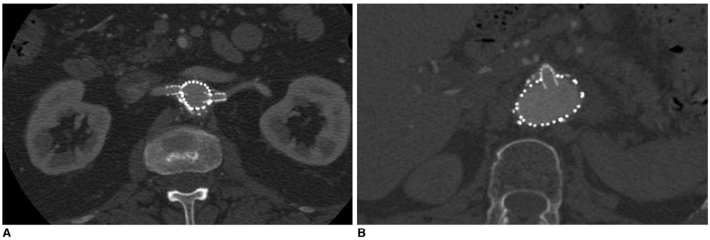
Fig. 2 2D axial images show small fenestrated stent inserted into bilateral renal arteries (A) and large fenestrated stent placed in superior mesenteric artery (B).

Fig. 3 Sagittal multiplanar reformation shows large fenestrated stent in superior mesenteric artery.

Fig. 4 Coronal surface-shaded display shows 3D relationship of fenestrated stent grafts relative to aortic branches. However, fenestrated renal stents (arrows) are hard to appreciate according to surface-shaded display visualization.
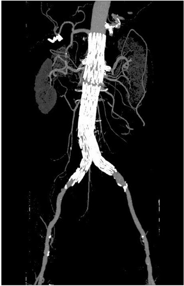
Fig. 5 Maximum-intensity projection image clearly shows fenestrated stents in bilateral renal arteries. However, intraluminal portion of stents is difficult to assess due to overlapping of high density stents.

Fig. 6 Volume rendering images demonstrate 3D relationship between fenestrated renal stents (red color) and aortic branches. Aorta and its branches are coded with green color.
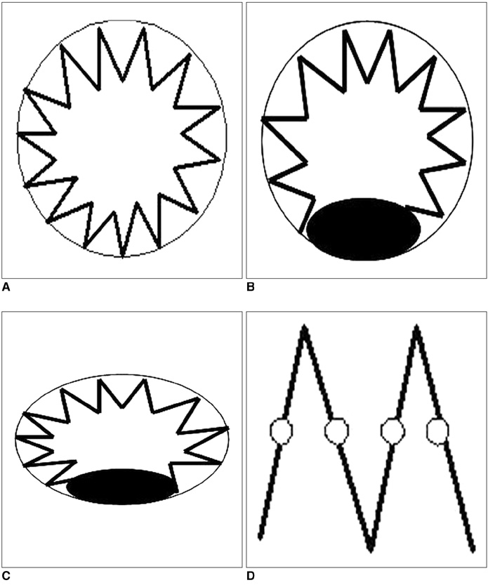
Fig. 7 Four types of fenestrated stent wires. A. Diagram of type I configuration showing normal circular appearance of stent wires. B. Type II circular configuration with flaring effect at lower part of stent wires. C. Type III elliptical appearance with flaring effect at lower part of stent wires. D. Type IV configuration without stents protruding into aortic lumen, and only markers are visualized. Type IV is most commonly seen for scallop fenestrations (standard width and double width scallops). Black eclipse inside circle simulates balloon dilatation effect during fenestrated procedures, which makes stents appear irregular.
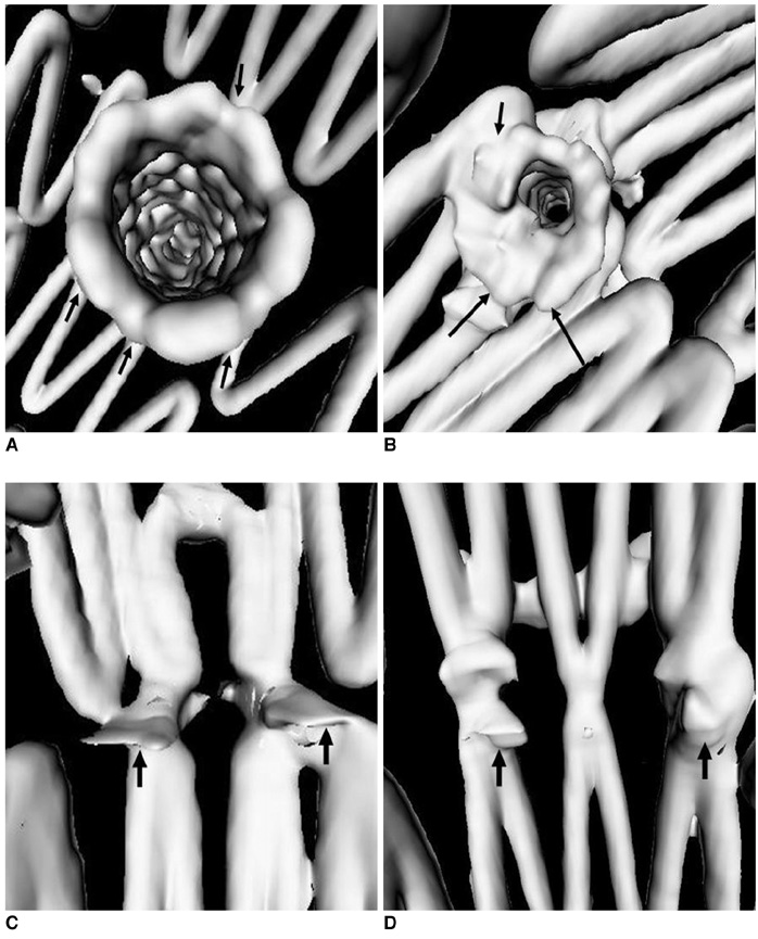
Fig. 8 Virtual intravascular endoscopy images provide intraluminal appearance of fenestrated vessel stents, which were observed as circular (A) and circular with irregular appearance of lower part (B) for small fenestrations, and standard scallop (C) and double width scallop fenestration (D) without intraluminal stent being observed. Short arrows in A and B indicate fenestrated vessel stents, while short arrows in C and D point to gold markers and artifacts resulting from markers in scalloped fenestrations. Long arrows indicate flaring effect.

Fig. 9 Length of stent protruding into aortic lumen (5.4 mm) could be measured on virtual intravascular endoscopy visualization.

Fig. 10 Detection of post-procedural abnormality. A. Example of deformed fenestrated renal stent (arrows). B. Another example showing no presence of intraluminal portion of fenestrated renal stent (arrows).
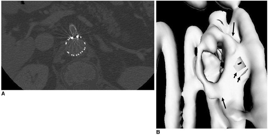
Fig. 11 Axial images (A) acquired with section thickness of 2.5 mm show apparent windmill artifacts present in fenestrated superior mesenteric stent. Corresponding virtual intravascular endoscopy (B) directly viewing fenestrated stent (long arrows) appears to be irregular with artifacts present (short arrows), resulting in overestimated thickness of stent wires.
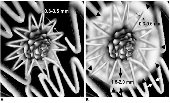
Fig. 12 Section thickness versus artifacts. A. Virtual intravascular endoscopy image with stent wire thickness similar or close to actual diameter after image processing. B. Artifacts caused by stent wires (arrowheads) on helical CT imaging make stent wires appear to be much thicker than actual diameter. Thin arrows indicate actual wire diameter, which ranges from 0.3 to 0.5 mm, while thick arrows refer to overestimated wire thickness, which is between 1.5 and 2.0 mm.
Reference
-
1. Parodi JC, Palmaz JC, Barone HD. Transfemoral intraluminal graft implantation for abdominal aortic aneurysms. Ann Vasc Surg. 1991. 5:491–499.2. Buth J, van Marrewijk CJ, Harris PL, Hop WC, Riambau V, Laheij RJ. EUROSTAR Collaborators. Outcome of endovascular abdominal aortic aneurysm repair in patients with conditions considered unfit for an open procedure: a report on the EUROSTAR experience. J Vasc Surg. 2002. 35:211–221.3. Lobato AC, Quick RC, Vaughn PL, Rodriguez-Lopez J, Douglas M, Diethrich EB. Transrenal fixation of aortic endografts: intermediate follow-up of a single e-center experience. J Endovasc Ther. 2000. 7:273–278.4. Bove PG, Long GW, Zelenock GB, Bendick PJ, Khoury MD, Burr MO, et al. Transrenal fixation of aortic stent-grafts for the treatment of infrarenal aortic aneurysmal disease. J Vasc Surg. 2000. 32:697–703.5. Browne TF, Hartley D, Purchas S, Rosenberg M, Van Schie G, Lawrence-Brown M. A fenestrated covered suprarenal aortic stent. Eur J Vasc Endovasc Surg. 1999. 18:445–449.6. Stanley BM, Semmens JB, Lawrence-Brown MM, Goodman MA, Hartley DE. Fenestration in endovascular grafts for aortic aneurysm repair: new horizons for preserving blood flow in branch vessels. J Endovasc Ther. 2001. 8:16–24.7. Anderson JL, Berce M, Hartley DE. Endoluminal aortic grafting with renal and superior mesenteric artery incorporation by graft fenestration. J Endovasc Ther. 2001. 8:3–15.8. Sun Z, Winder RJ, Kelly BE, Ellis PK, Kennedy PT, Hirst DG. Diagnostic value of CT virtual intravascular endoscopy in aortic stent-grafting. J Endovasc Ther. 2004. 11:13–25.9. Sun Z. 3D multislice CT angiography in post-aortic stent grafting: a pictorial essay. Korean J Radiol. 2006. 7:205–211.10. Sun Z. Three-dimensional visualization of suprarenal aortic tent-grafts: evaluation of migration in midterm follow-up. J Endovasc Ther. 2006. 13:85–93.11. Sun Z, Winder RJ, Kelly BE, Ellis PK, Hirst DG. CT virtual intravascular endoscopy of abdominal aortic aneurysms treated with suprarenal endovascular stent grafting. Abdom Imaging. 2003. 28:580–587.12. Sun Z. Transrenal fixation of aortic stent-grafts: current status and future directions. J Endovasc Ther. 2004. 11:539–549.13. Sun Z. Helical CT angiography of abdominal aortic aneurysms treated with suprarenal stent grafting. Cardiovasc Intervent Radiol. 2003. 26:290–295.14. Sun Z, Allen YB, Nadkarni S, Knight R, Hartley D, Lawrence-Brown MM. CT virtual intravascular endoscopy in the visualization of fenestrated stent-grafts. J Endovasc Ther. 2008. 15:42–51.15. Sun Z, Mwipatayi BP, Semmens JB, Lawrence-Brown MM. Short to midterm outcomes of fenestrated endovascular grafts in the treatment of abdominal aortic aneurysms: a systematic review. J Endovasc Ther. 2006. 13:747–753.16. Semmens JB, Lawrence-Brown MM, Hartley DE, Allen YB, Green R, Nadkarni S. Outcomes of fenestrated endografts in the treatment of abdominal aortic aneurysm in Western Australia (1997-2004). J Endovasc Ther. 2006. 13:320–329.17. Sun Z, Allen YB, Mwipatayi BP, Hartley DE, Lawrence-Brown MM. Multislice CT angiography in the follow-up of fenestrated endovascular grafts: effect of slice thickness on 2D and 3D visualization of the fenestrated stents. J Endovasc Ther. 2008. 15:417–426.
- Full Text Links
-
- Actions
-
Cited
- CITED
-
- Close
- Share
-
- Similar articles
-
- 3D Multislice CT Angiography in Post-Aortic Stent Grafting: A Pictorial Essay
- Endovascular Repair of Thoracic Aortic Aneurysm Using a Custom-made Fenestrated Stent Graft to Preserve the Left Subclavian Artery
- Multislice CT Virtual Intravascular Endoscopy for Assessing Pulmonary Embolisms: a Pictorial Review
- Endovascular Treatment of Abdominal Aortic Aneurysm
- Fenestrated Stent Graft Repair of Abdominal Aortic Aneurysm: Hemodynamic Analysis of the Effect of Fenestrated Stents on the Renal Arteries
