Three-dimensional finite element analysis of the deformation of the human mandible: a preliminary study from the perspective of orthodontic mini-implant stability
- Affiliations
-
- 1Division of Orthodontics, Department of Dentistry, Asan Medical Center, University of Ulsan College of Medicine, Seoul, Korea. ssjmail@amc.seoul.kr
- 2Division of Prosthodontics, Department of Dentistry, Asan Medical Center, University of Ulsan College of Medicine, Seoul, Korea.
- 3Department of Orthodontics, College of Dentistry, Yonsei University, Seoul, Korea.
- KMID: 1435410
- DOI: http://doi.org/10.4041/kjod.2012.42.4.159
Abstract
OBJECTIVE
The aims of this study were to investigate mandibular deformation under clenching and to estimate its effect on the stability of orthodontic mini-implants (OMI).
METHODS
Three finite element models were constructed using computed tomography (CT) images of 3 adults with different mandibular plane angles (A, low; B, average; and C, high). An OMI was placed between #45 and #46 in each model. Mandibular deformation under premolar and molar clenching was simulated. Comparisons were made between peri-orthodontic mini-implant compressive strain (POMI-CSTN) under clenching and orthodontic traction forces (150 g and 200 g).
RESULTS
Three models with different mandibular plane angles demonstrated different functional deformation characteristics. The compressive strains around the OMI were distributed mesiodistally rather than occlusogingivally. In model A, the maximum POMI-CSTN under clenching was observed at the mesial aspect of #46 (1,401.75 microstrain [microE]), and similar maximum POMI-CSTN was observed under a traction force of 150 g (1,415 microE).
CONCLUSIONS
The maximum POMI-CSTN developed by clenching failed to exceed the normally allowed compressive cortical bone strains; however, additional orthodontic traction force to the OMI may increase POMI-CSTN to compromise OMI stability.
Figure
-

Figure 1 Segmentation and 3-dimensional surface generation with Bionix program (A) and finite element model construction using Hypermesh program (B).
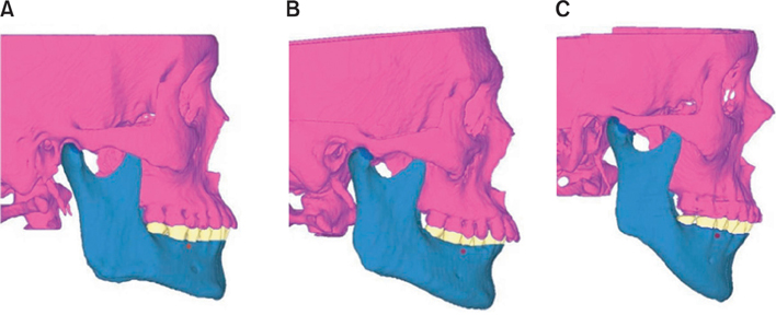
Figure 2 The 3 finite element models. A, Model A (low angle); B, model B (average angle); C, model C (high angle).

Figure 3 The position and insertion angulation of the OMI in the FE model, and schematic modeling of the temporomandibular joint. A, Buccal view; B, occlusal view; C, cross-sectional view of #45 and #46; D, cross-sectional view of the right temporomandibular joint.

Figure 4 The cylindrical coordinate system for the application of orthotropic material properties. A, The cross-section of the mandibular body was selected at half its height. B, Five ellipses were drawn that best fit the right and left sections. The 5 centers of the ellipses and the 5 ratios between the lengths of the semimajor axes and the semiminor axes were calculated. Solid arrows indicate the material x-axis (x'). Dotted arrows indicate the material y-axis (y').
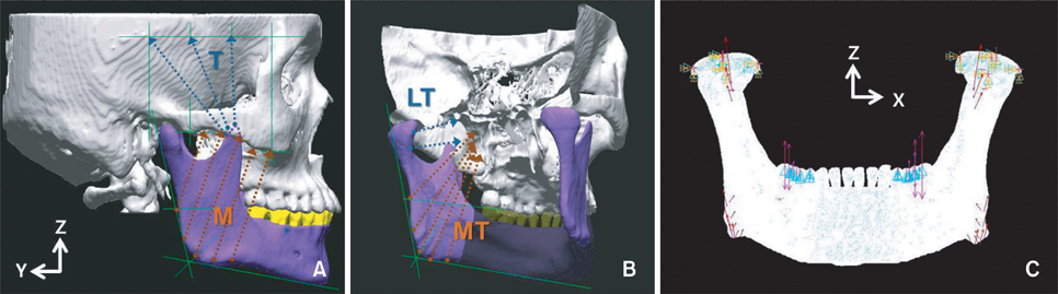
Figure 5 Four jaw-closing muscles and their lines of action. A, M: masseter muscle, T: temporal muscle; B, MT: medial pterygoid muscle, LT: lateral pterygoid muscle; C, boundary conditions for the clenching simulation.
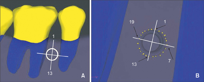
Figure 6 Twenty-four reference nodes of the cortical bone. Reference node 1 is at the most occlusal direction.
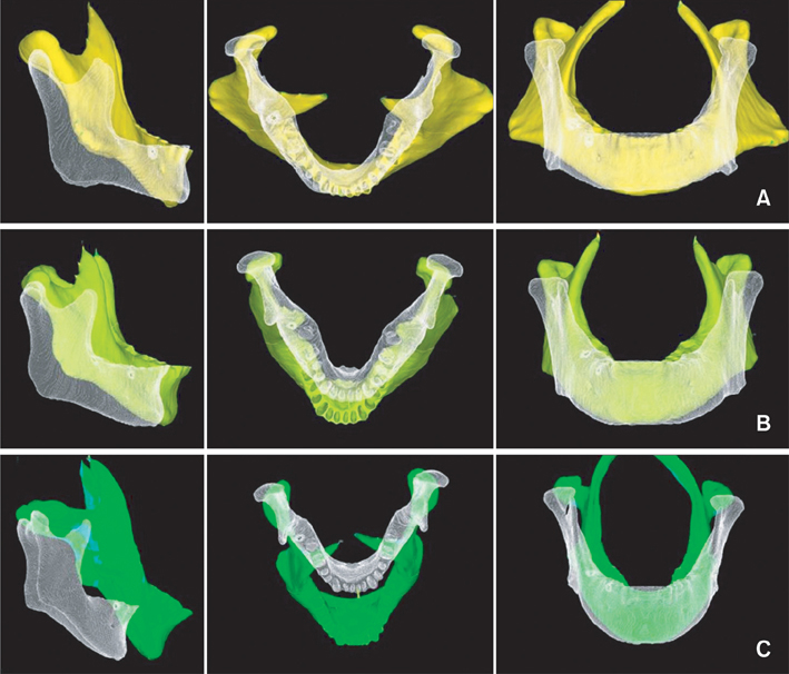
Figure 7 The deformed shape (colored) with the undeformed model (white) after simulated molar clenching with orthotropic material properties (100× magnification). A, Model A; B, model B; C, model C.
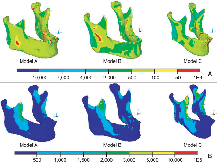
Figure 8 Comparison of the strain distribution of the mandible under clenching in 3 models. A, Compressive strain; B, tensile strain. Unit: microstrain (µE).

Figure 9 Comparison of the peri-orthodontic mini-implant compressive strain using a polar line chart. Red dotted line-model A (isotropic); red solid line-model A (orthotropic); blue dotted line-model B (isotropic); blue solid line-model B (orthotropic); green dotted line-model A (isotropic); green solid line-model A (orthotropic). Unit: microstrain (µE).
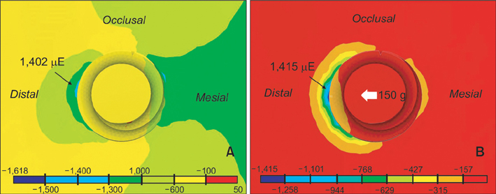
Figure 10 Comparison of peri-orthodontic mini-implant compressive strain with a contour plot in model. A, During clenching; B, under a traction force of 150 g. Unit: microstrain (µE).
Reference
-
1. Creekmore TD, Eklund MK. The possibility of skeletal anchorage. J Clin Orthod. 1983. 17:266–269.2. Kanomi R. Mini-implant for orthodontic anchorage. J Clin Orthod. 1997. 31:763–767.3. Kuroda S, Sugawara Y, Deguchi T, Kyung HM, Takano-Yamamoto T. Clinical use of miniscrew implants as orthodontic anchorage: success rates and postoperative discomfort. Am J Orthod Dentofacial Orthop. 2007. 131:9–15.
Article4. Miyawaki S, Koyama I, Inoue M, Mishima K, Sugahara T, Takano-Yamamoto T. Factors associated with the stability of titanium screws placed in the posterior region for orthodontic anchorage. Am J Orthod Dentofacial Orthop. 2003. 124:373–378.
Article5. Chen Y, Kyung HM, Zhao WT, Yu WJ. Critical factors for the success of orthodontic mini-implants: a systematic review. Am J Orthod Dentofacial Orthop. 2009. 135:284–291.
Article6. Cheng SJ, Tseng IY, Lee JJ, Kok SH. A prospective study of the risk factors associated with failure of mini-implants used for orthodontic anchorage. Int J Oral Maxillofac Implants. 2004. 19:100–106.7. Korioth TW, Hannam AG. Deformation of the human mandible during simulated tooth clenching. J Dent Res. 1994. 73:56–66.
Article8. Mo SS, Ahn HT, Lee JS, Chung YS, Moon YS, Pae EK, et al. Morphological characteristics of the upper airway and pressure drop analysis using 3D CFD in OSA patients. Korean J Orthod. 2010. 40:66–76.
Article9. Sung SJ, Jang GW, Chun YS, Moon YS. Effective enmasse retraction design with orthodontic mini-implant anchorage: a finite element analysis. Am J Orthod Dentofacial Orthop. 2010. 137:648–657.
Article10. Bonnet AS, Postaire M, Lipinski P. Biomechanical study of mandible bone supporting a four-implant retained bridge: finite element analysis of the influence of bone anisotropy and foodstuff position. Med Eng Phys. 2009. 31:806–815.
Article11. Gray H, Clemente CD. Anatomy of the human body. 1985. 30th ed. Philadelphia: Lea & Febiger.12. Gilroy AM, MacPherson BR, Ross LM, Schuenke M, Schulte E, Schumacher U. Atlas of Anatomy. 2008. New York: Thieme.13. Hylander WL. The functional significance of primate mandibular form. J Morphol. 1979. 160:223–240.
Article14. O'Mahony AM, Williams JL, Spencer P. Anisotropic elasticity of cortical and cancellous bone in the posterior mandible increases peri-implant stress and strain under oblique loading. Clin Oral Implants Res. 2001. 12:648–657.15. Tsunori M, Mashita M, Kasai K. Relationship between facial types and tooth and bone characteristics of the mandible obtained by CT scanning. Angle Orthod. 1998. 68:557–562.16. Sato H, Kawamura A, Yamaguchi M, Kasai K. Relationship between masticatory function and internal structure of the mandible based on computed tomography findings. Am J Orthod Dentofacial Orthop. 2005. 128:766–773.
Article17. Masumoto T, Hayashi I, Kawamura A, Tanaka K, Kasai K. Relationships among facial type, buccolingual molar inclination, and cortical bone thickness of the mandible. Eur J Orthod. 2001. 23:15–23.
Article18. Moon CH, Park HK, Nam JS, Im JS, Baek SH. Relationship between vertical skeletal pattern and success rate of orthodontic mini-implants. Am J Orthod Dentofacial Orthop. 2010. 138:51–57.
Article19. Proffit WR, Fields HW, Nixon WL. Occlusal forces in normal- and long-face adults. J Dent Res. 1983. 62:566–570.
Article20. Braun S, Bantleon HP, Hnat WP, Freudenthaler JW, Marcotte MR, Johnson BE. A study of bite force, part 2: Relationship to various cephalometric measurements. Angle Orthod. 1995. 65:373–377.21. van Spronsen PH. Long-face craniofacial morphology: Cause or effect of weak masticatory musculature? Semin Orthod. 2010. 16:99–117.
Article22. Frost HM. Suggested fundamental concepts in skeletal physiology. Calcif Tissue Int. 1993. 52:1–4.
Article23. Frost HM. Transient-steady state phenomena in microdamage physiology: a proposed algorithm for lamellar bone. Calcif Tissue Int. 1989. 44:367–381.
Article24. Frost HM. Wolff's Law and bone's structural adaptations to mechanical usage: an overview for clinicians. Angle Orthod. 1994. 64:175–188.25. Kim KD, Yu WJ, Park HS, Kyung HM, Kwon OW. Optimization of orthodontic microimplant thread design. Korean J Orthod. 2011. 41:25–35.
Article26. Wawrzinek C, Sommer T, Fischer-Brandies H. Microdamage in cortical bone due to the overtightening of orthodontic microscrews. J Orofac Orthop. 2008. 69:121–134.
Article
- Full Text Links
-
- Actions
-
Cited
- CITED
-
- Close
- Share
-
- Similar articles
-
- Contact non-linear finite element model analysis of initial stability of mini implant
- Three-dimensional finite element analysis for stress distribution on the diameter of orthodontic mini-implants and insertion angle to the bone surface
- Biomechanical analysis of distalization of mandibular molars by placing a mini-plate: A finite element study
- Three-dimensional finite element analysis of implant-supported crown in fibula bone model
- A study on the finite element analysis and bone formation of the apically expandable implant
