A New and Simple Practical Plane Dividing Hepatic Segment 2 and 3 of the Liver: Evaluation of Its Validity
- Affiliations
-
- 1Department of Radiology and Institute of Radiation Medicine, Seoul National University College of Medicine, Clinical Research Institute, Seoul National University Hospital, Seoul, Korea. chungjw@radcom.snu.ac.kr
- KMID: 1110727
- DOI: http://doi.org/10.3348/kjr.2007.8.4.302
Abstract
OBJECTIVE
The conventional method of dividing hepatic segment 2 (S2) and 3 (S3) is subjective and CT interpretation is unclear. The purpose of our study was to test the validity of our hypothesis that the actual plane dividing S2 and S3 is a vertical plane of equal distance from the S2 and S3 portal veins in clinical situations. MATERIALS AND METHODS: We prospectively performed thin-section iodized-oil CT immediately after segmental chemoembolization of S2 or S3 in 27 consecutive patients and measured the angle of intersegmental plane on sagittal multiplanar reformation (MPR) images to verify its vertical nature. Our hypothetical plane dividing S2 and S3 is vertical and equidistant from the S2 and S3 portal veins (vertical method). To clinically validate this, we retrospectively collected 102 patients with small solitary hepatocellular carcinomas (HCC) on S2 or S3 the segmental location of which was confirmed angiographically. Two reviewers predicted the segmental location of each tumor at CT using the vertical method independently in blind trials. The agreement between CT interpretation and angiographic results was analyzed with Kappa values. We also compared the vertical method with the horizontal one. RESULTS: In MPR images, the average angle of the intersegmental plane was slanted 15 degrees anteriorly from the vertical plane. In predicting the segmental location of small HCC with the vertical method, the Kappa value between CT interpretation and angiographic result was 0.838 for reviewer 1 and 0.756 for reviewer 2. Inter-observer agreement was 0.918. The vertical method was superior to the horizontal method for localization of HCC in the left lobe (p < 0.0001 for reviewers 1 and 2). CONCLUSION: The proposed vertical plane equidistant from S2 and S3 portal vein is simple to use and useful for dividing S2 and S3 of the liver.
Keyword
MeSH Terms
-
Adult
Aged
Aged, 80 and over
Angiography, Digital Subtraction
Antibiotics, Antineoplastic/administration & dosage
Carcinoma, Hepatocellular/blood supply/radiography/therapy
Chemoembolization, Therapeutic
Contrast Media
Doxorubicin/administration & dosage
Female
Humans
Iodized Oil/diagnostic use
Liver/*blood supply/*radiography
Liver Neoplasms/blood supply/radiography/therapy
Male
Middle Aged
Prospective Studies
Registries
Retrospective Studies
*Tomography, Spiral Computed
Figure
-
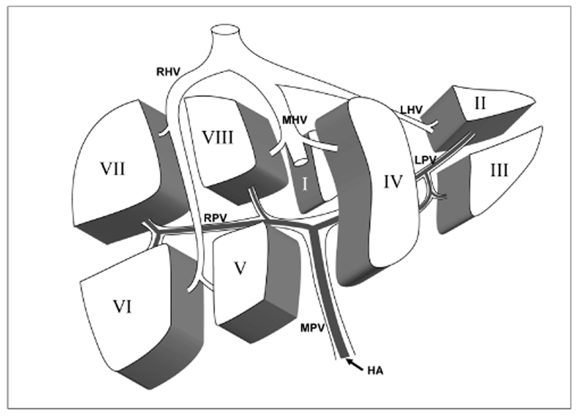
Fig. 1 Diagram of the hepatic segments (I-VIII) with their portal venous branches, separated by the hepatic veins and the transverse fissure. Anterior view of the liver. Segments are numbered in a counterclockwise direction (RHV = right hepatic vein, MHV = middle hepatic vein, LHV = left hepatic vein, RPV = right portal vein, LPV = left portal vein, MPV = main portal vein, HA = hepatic artery).

Fig. 2 Intersegmental plane depicted on iodized-oil CT in a 61-year-old female with hepatocellular carcinoma in the left lateral segment. A. Portal venous phase CT image shows the umbilical portion of the left portal vein. B. Small peripheral rim-enhancing tumor nodule with central low attenuation (arrows) is noted in the section below the umbilical portion. C. Proper hepatic arteriogram shows the small tumor staining below the S3 hepatic artery. However, selective S3 hepatic arteriogram (no figure shown) shows no tumor staining. D. Selective S2 hepatic arteriogram shows the tumor staining. Segmental chemoembolization of S2 was performed. E. Sagittal multiplanar reformation image of thin-section iodized-oil CT performed immediately after segmental chemoembolization shows the segmental distribution of the iodized oil in S2 and dense iodized oil uptake to the tumor without any defect (arrow). F. The intersegmental plane between S2 and S3 (thin continuous line) was almost vertical (angle: -2 degree). '+' was defined as the anterior direction and '-' as the posterior direction.

Fig. 3 How to create a hypothetical vertical plane equidistant from S2 and S3 portal veins in a 52-year-old female with hepatocellular carcinoma in the left lateral segment. A. Axial maximum intensity projection image shows S2 and S3 portal vein branching from the umbilical portion and the location of the hypothetical vertical plane (line), which is vertical and of equal distance from S2 and S3 portal veins. Small hepatocellular carcinoma nodule (arrow) is noted between S2 and S3 portal vein and anterior to the plane. B. The first step in creating the plane is to draw a line along S2 and S3 portal veins on the axial portal phase helical CT (thin lines). It is a prerequisite to use the cine mode in PACS viewer. Then, we can easily create a line (thick line) in equal distance from the two lines, which is the hypothetical vertical plane tested in this study. C. By scrolling images, we can reach the axial plane containing the tumor. Small enhancing nodule (arrows) is noted at the peripheral area of the left lateral segment above the umbilical portion. By applying the hypothetical plane in this image, we can predict the nodule is located in S3 because it is anterior to the plane. D. A proper hepatic arterial angiogram shows a hypervascular tumor (black arrow) just below the diaphragm above S2 hepatic artery (white arrow with S2). E. However, a selective S2 hepatic arteriogram shows no tumor staining. Tumor staining was detected at the selective S3 hepatic arteriogram (not shown) and segmental chemoembolization of S3 was performed. F. Follow-up iodized-oil CT after segmental transcatheter atterial chemoembolization shows homogenous deposition of iodized oil in the tumor.
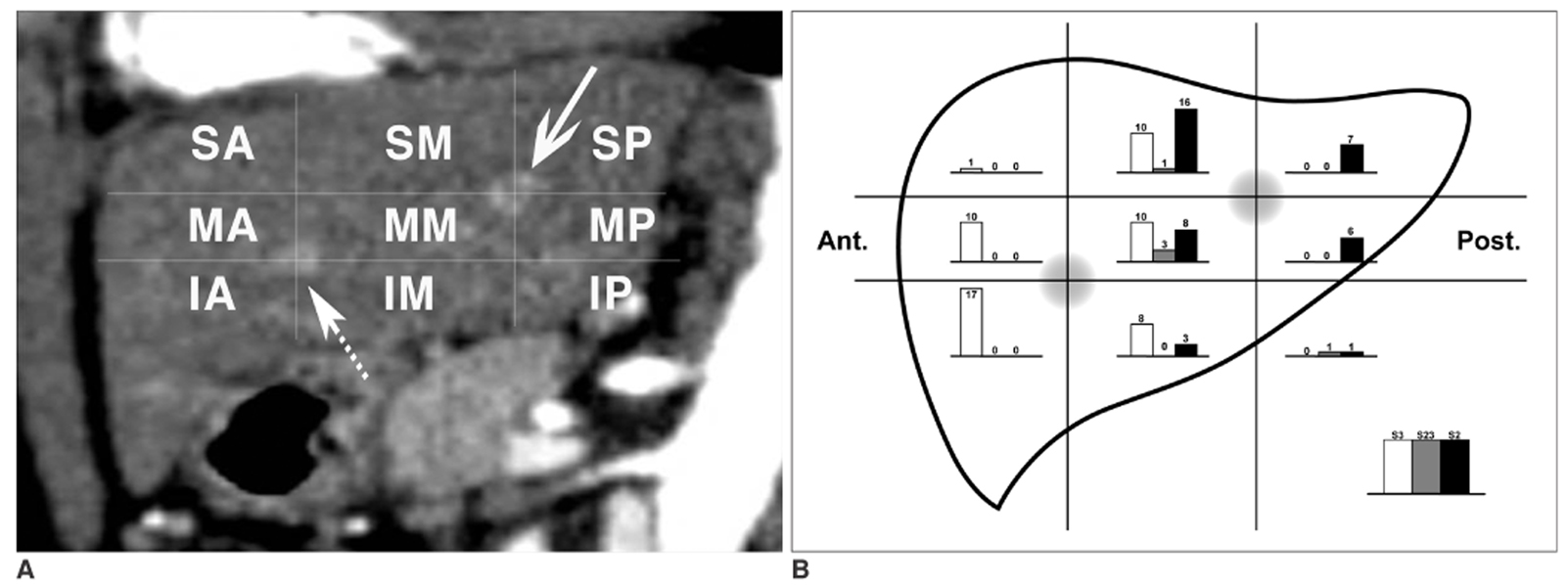
Fig. 4 How to determine nine zones of the left lateral segment in the sagittal plane based on S2 and S3 portal veins and the distribution of their tumor-feeding arteries in each zone. A. By the standard of S2 portal vein (continuous arrow) and S3 portal vein (dashed arrow), the left lateral segment of the liver was divided into nine zones: superior-anterior (SA), superior-middle (SM), superior-posterior (SP), middle-anterior (MA), middle-middle (MM), middle-posterior (MP), inferior-anterior (IA), inferior-middle (IM), and inferior-posterior (IP). B. The distribution of tumor-feeding arteries of 102 hepatocellular carcinomas are illustrated in the schematic diagram of the nine zones.
Reference
-
1. Couinaud C. Surgical Anatomy of the Liver. 1989. Revised. Paris, France: Personal.2. Bismuth H. Surgical anatomy and anatomical surgery of the liver. World J Surg. 1992. 6:3–9.3. Soyer P. Segmental anatomy of the liver: utility of a nomenclature accepted worldwide. AJR Am J Roentgenol. 1993. 161:572–573.4. Nelson RC, Chezmar JL, Sugarbaker PH, Murray DR, Bernardino ME. Preoperative localization of focal liver lesions to specific liver segments: utility of CT during arterial portography. Radiology. 1990. 176:89–94.5. Lafortune M, Madore E, Patriquin H, Breton G. Segmental anatomy of the liver: a sonographic approach to the Couinaud nomenclature. Radiology. 1991. 181:443–448.6. Ferrucci JT. Liver tumor imaging: current concepts. AJR Am J Roentgenol. 1990. 155:473–484.7. Russell E, Yrizzary JM, Montalvo BM, Guerra JJ Jr, al-Refai F. Left hepatic duct anatomy: implications. Radiology. 1990. 174:353–356.8. Soyer P, Roche A, Gad M, Shapeero L, Breittmayer F, Elias D, et al. Preoperative segmental localization of hepatic metastases: utility of three-dimensional CT during arterial portography. Radiology. 1991. 180:653–658.9. Fischer L, Cardenas C, Thorn M, Benner A, Grenacher L, Vetter M, et al. Limits of Couinaud's liver segment classification: a quantitative computer-based three-dimensional analysis. J Comput Assist Tomogr. 2002. 26:962–967.10. Fasel JH, Selle D, Evertsz CJ, Terrier F, Peitgen HO, Gailloud P. Segmental anatomy of the liver: poor correlation with CT. Radiology. 1998. 206:151–156.11. Gupta SC, Gupta CD, Arora AK. Intrahepatic branching patterns of portal vein. A study by corrosion cast. Gastroenterology. 1977. 72:621–624.12. Lamade W, Glombitza G, Fischer L, Chiu P, Cardenas CE, Thorn M, et al. The impact of 3-dimensional reconstructions on operation planning in liver surgery. Arch Surg. 2000. 135:1256–1261.13. Kundel HL, Polansky M. Measurement of observer agreement. Radiology. 2003. 228:303–308.14. Ohashi I, Ina H, Okada Y, Yoshida T, Gomi N, Himeno Y, et al. Segmental anatomy of the liver under the right diaphragmatic dome: evaluation with axial CT. Radiology. 1996. 200:779–783.15. Downey PR. Radiologic identification of liver segments. AJR Am J Roentgenol. 1994. 163:1267–1268.16. International Anatomical Nomenclature Committee (IANC). Nomina anatomica. 1983. 5th ed. Baltimore, MD: Williams and Wilkins;A37.17. Bennett WF, Bova JG, Petty L, Martin EW Jr. Preoperative 3D rendering of MR imaging in liver metastases. J Comput Assist Tomogr. 1991. 15:979–984.18. van Leeuwen MS, Fernandez MA, van Es HW, Stokking R, Dillon EH, Feldberg MA. Variations in venous and segmental anatomy of the liver: two- and three-dimensional MR imaging in healthy volunteers. AJR Am J Roentgenol. 1994. 162:1337–1345.19. Deshpande RR, Heaton ND, Rela M. Surgical anatomy of segmental liver transplantation. Br J Surg. 2002. 89:1078–1088.
- Full Text Links
-
- Actions
-
Cited
- CITED
-
- Close
- Share
-
- Similar articles
-
- Evaluation of liver scanning image in various hepatic disease
- Portal Venous Anatomy in Right Lobe of the Liver: CT Evaluation
- Analysis of Anatomic Variation of the Hepatic Artery by Spiral CT Hepatic Arteriography, Lipiodol CT, and Angiography
- Variations in the origin of middle hepatic artery: a cadaveric study and implications for living donor liver transplantation
- A case of simple type Caroli's disease confined to one segment of the liver
