Korean J Orthod.
2024 Mar;54(2):108-116. 10.4041/kjod23.217.
Three-dimensional finite element analysis on the effects of maxillary protraction with an individual titanium plate at multiple directions and locations
- Affiliations
-
- 1Department of Orthodontics, School of Stomatology, Capital Medical University, Beijing, China
- KMID: 2554367
- DOI: http://doi.org/10.4041/kjod23.217
Abstract
Objective
A three-dimensional-printed individual titanium plate was applied for maxillary protraction to eliminate side effects and obtain the maximum skeletal effect. This study aimed to explore the stress distribution characteristics of sutures during maxillary protraction using individual titanium plates in various directions and locations.
Methods
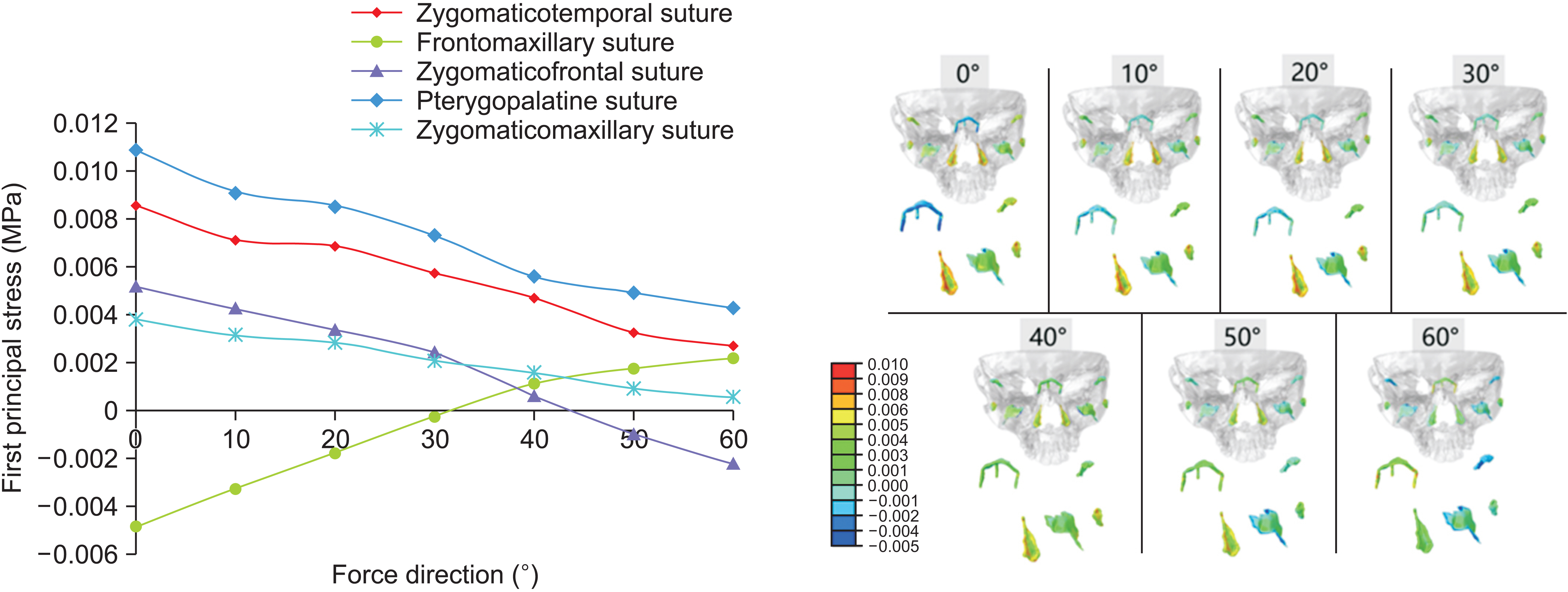
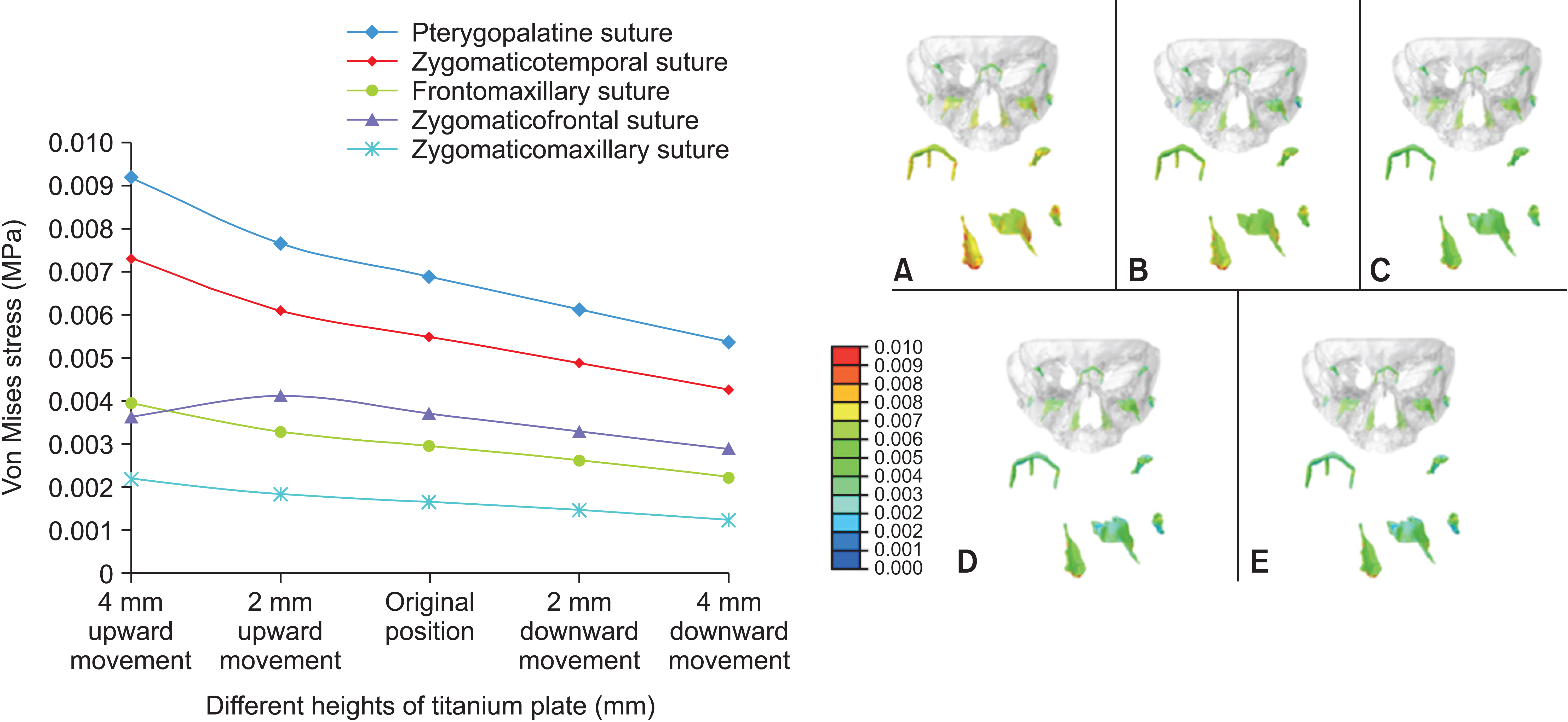
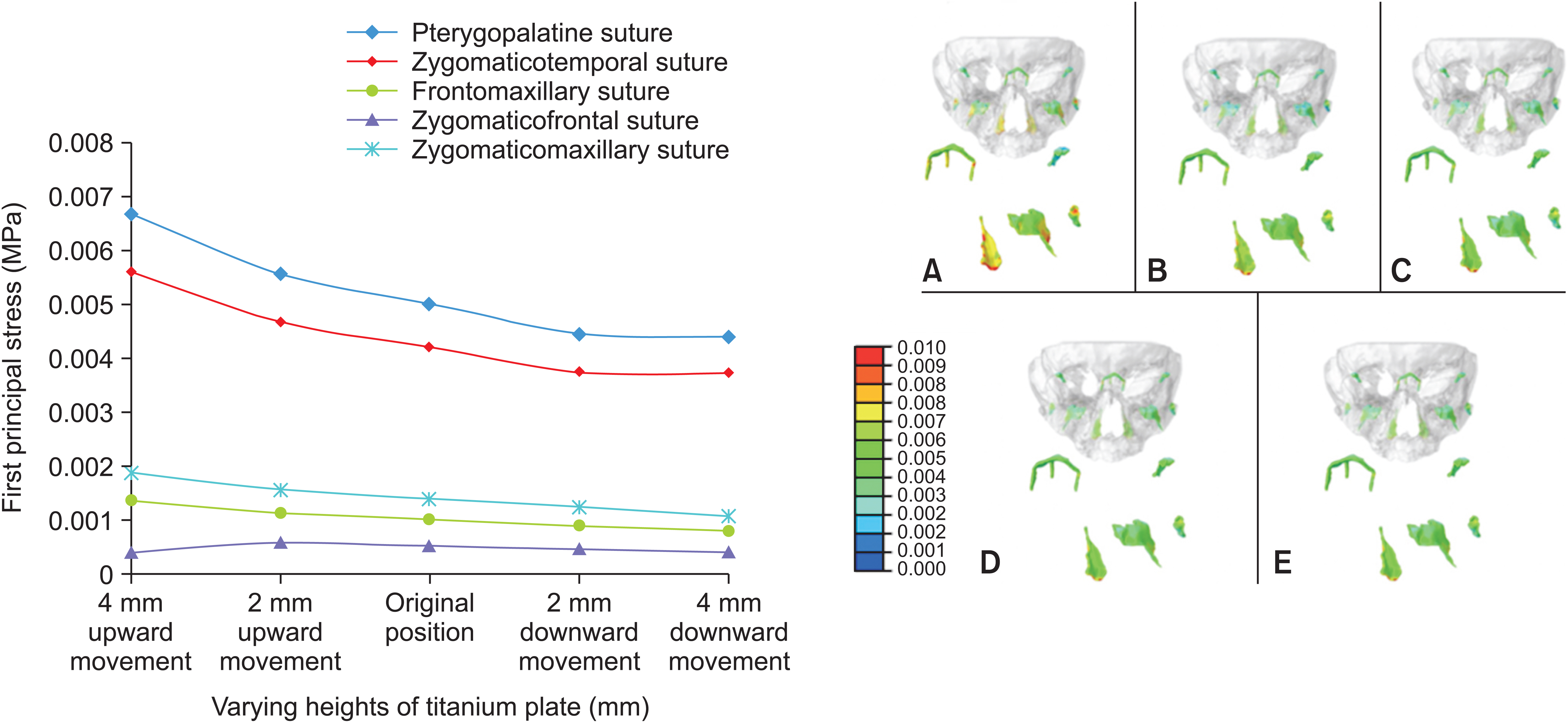
A protraction force of 500 g per side was applied at forward and downward angles between 0° and 60° with respect to the Frankfort horizontal plane, after which the titanium plate was moved 2 and 4 mm upward and downward, respectively. Changes in sutures with multiple protraction directions and various miniplate heights were quantified to analyze their impact on the maxillofacial bone.
Results
Protraction angle of 0–30° with respect to the Frankfort horizontal plane exhibited a tendency for counterclockwise rotation in the maxilla. At a 40° protraction angle, translational motion was observed in the maxilla, whereas protraction angles of 50–60° tended to induce clockwise rotation in the maxilla. Enhanced protraction efficiency at the lower edge of the pyriform aperture was associated with increased height of individual titanium plates.
Conclusions
Various protraction directions are suitable for patients with different types of vertical bone surfaces. Furthermore, when the titanium plate was positioned lower, the protraction force exhibited an increase.
Figure
Reference
-
1. Dietrich UC. 1970; Morphological variability of skeletal Class 3 relationships as revealed by cephalometric analysis. Rep Congr Eur Orthod Soc. 46:131–43. https://pubmed.ncbi.nlm.nih.gov/5287485/.2. Sar C, Arman-Özçırpıcı A, Uçkan S, Yazıcı AC. 2011; Comparative evaluation of maxillary protraction with or without skeletal anchorage. Am J Orthod Dentofacial Orthop. 139:636–49. https://doi.org/10.1016/j.ajodo.2009.06.039. DOI: 10.1016/j.ajodo.2009.06.039.
Article3. Cevidanes L, Baccetti T, Franchi L, McNamara JA Jr, De Clerck H. 2010; Comparison of two protocols for maxillary protraction: bone anchors versus face mask with rapid maxillary expansion. Angle Orthod. 80:799–806. https://doi.org/10.2319/111709-651.1. DOI: 10.2319/111709-651.1. PMCID: PMC2930261.
Article4. Zhou YH, Ding P, Lin Y, Qiu L. 2007; Preliminary study on miniplate implant anchorage for maxillary protraction. Chin J Orthod. 14:102–5. Chinese. https://caod.oriprobe.com/articles/52754/Preliminary_study_on_miniplate_implant_anchorage_f.htm.5. Liang S, Xie X, Wang F, Chang Q, Wang H, Bai Y. 2020; Maxillary protraction using customized mini-plates for anchorage in an adolescent girl with skeletal Class III malocclusion. Korean J Orthod. 50:346–55. https://doi.org/10.4041/kjod.2020.50.5.346. DOI: 10.4041/kjod.2020.50.5.346. PMID: 32938827. PMCID: PMC7500574.
Article6. Liang SR, Wang F, Zhou DQ, Chang S, Bai YX. 2017; Three-dimensional printed miniplate used for maxillary protraction. Zhonghua Kou Qiang Yi Xue Za Zhi. 52:753–5. Chinese. https://pubmed.ncbi.nlm.nih.gov/29275570/. DOI: 10.3760/cma.j.issn.1002-0098.2017.12.008. PMID: 29275570.7. Yu HS, Baik HS, Sung SJ, Kim KD, Cho YS. 2007; Three-dimensional finite-element analysis of maxillary protraction with and without rapid palatal expansion. Eur J Orthod. 29:118–25. https://doi.org/10.1093/ejo/cjl057. DOI: 10.1093/ejo/cjl057. PMID: 17218719.
Article8. Lee NK, Baek SH. 2012; Stress and displacement between maxillary protraction with miniplates placed at the infrazygomatic crest and the lateral nasal wall: a 3-dimensional finite element analysis. Am J Orthod Dentofacial Orthop. 141:345–51. https://doi.org/10.1016/j.ajodo.2011.07.021. DOI: 10.1016/j.ajodo.2011.07.021. PMID: 22381495.
Article9. Tanne K, Hiraga J, Sakuda M. 1989; Effects of directions of maxillary protraction forces on biomechanical changes in craniofacial complex. Eur J Orthod. 11:382–91. https://doi.org/10.1093/oxfordjournals.ejo.a036010. DOI: 10.1093/oxfordjournals.ejo.a036010.
Article10. Kim KY, Bayome M, Park JH, Kim KB, Mo SS, Kook YA. 2015; Displacement and stress distribution of the maxillofacial complex during maxillary protraction with buccal versus palatal plates: finite element analysis. Eur J Orthod. 37:275–83. https://doi.org/10.1093/ejo/cju039. DOI: 10.1093/ejo/cju039.
Article11. Kircelli BH, Pektas ZO. 2008; Midfacial protraction with skeletally anchored face mask therapy: a novel approach and preliminary results. Am J Orthod Dentofacial Orthop. 133:440–9. https://doi.org/10.1016/j.ajodo.2007.06.011. DOI: 10.1016/j.ajodo.2007.06.011. PMID: 18331946.
Article12. Gautam P, Valiathan A, Adhikari R. 2009; Maxillary protraction with and without maxillary expansion: a finite element analysis of sutural stresses. Am J Orthod Dentofacial Orthop. 136:361–6. https://doi.org/10.1016/j.ajodo.2008.02.021. DOI: 10.1016/j.ajodo.2008.02.021. PMID: 19732670.
Article13. Lin QI, Jing-Hua T, Zhen-Jin Z, Yang Z. 2013; Study of stress distribution of craniofacial sutures following maxillary protraction with palatal expansion- a three-dimensional FEM study. Chin J Med Phys. 30:3933–5. http://zgyxwlxzz.paperopen.com/en/oa/DArticle.aspx?type=view&id=201301024.14. Qu Y, Liu J, Yang S, Huang Y. 2016; 3-D finite element study on maxillary body protraction using implant anchorage. J Pract Stomatol. 32:58–62. https://caod.oriprobe.com/articles/48123795/3_D_finite_element_study_on_maxillary_body_protrac.htm.15. Yan X, He W, Lin T, Liu J, Bai X, Yan G, et al. 2013; Three-dimensional finite element analysis of the craniomaxillary complex during maxillary protraction with bone anchorage vs conventional dental anchorage. Am J Orthod Dentofacial Orthop. 143:197–205. https://doi.org/10.1016/j.ajodo.2012.09.019. DOI: 10.1016/j.ajodo.2012.09.019. PMID: 23374926.
Article16. Zhang GH, Cai Z, Lu Q. 2000; Three-dimensional finite element method study on the maxillary protraction: the direction of the protraction. J Med Biomech. 15:208–11. http://www.mechanobiology.cn/yyswlxen/article/abstract/200004004?st=article_issue.17. Miyasaka J, Tanne K, Tsutsumi S, Sakuda M. 1986; Finite element analysis of the biomechanical effects of orthopedic forces on the craniofacial skeleton. Construction of a 3-dimensional finite element model of the craniofacial skeleton. Osaka Daigaku Shigaku Zasshi. 31:393–402. Japanese. https://pubmed.ncbi.nlm.nih.gov/3469386/.18. Zou M, Lin WJ. 2011; A three-dimensional finite element study on the influence of different protraction force on cranio-maxillary complex. Shanghai Kou Qiang Yi Xue. 20:88–92. Chinese. https://pubmed.ncbi.nlm.nih.gov/21451906/.19. Kambara T. 1977; Dentofacial changes produced by extraoral forward force in the Macaca irus. Am J Orthod. 71:249–77. https://doi.org/10.1016/0002-9416(77)90187-7. DOI: 10.1016/0002-9416(77)90187-7. PMID: 402814.
Article
- Full Text Links
- Actions
-
Cited
- CITED
-
- Close
- Share
- Similar articles
-
- Displacement and stress distribution of the maxillofacial complex during maxillary protraction using palatal plates: A three-dimensional finite element analysis
- Effects of maxillary protraction on the displacement of the maxilla
- A study on stress distribution in IMZ implant with a plastic or a titanium IME using finite element analysis
- Stress distribution following face mask application using different finite element models according to Hounsfield unit values in CT images
- THE THREE DIMENSIONAL FINITE ELEMENT ANALYSIS OF STRESS DISTRIBUTION AND DISPLACEMENT IN MANDIBLE ACCORDING TO TREATMENT MODALITIES OF MANDIBULAR ANGLE FRACTURES

