Recent Issues in Musculoskeletal Anatomy Research and Correlation with MRI
- Affiliations
-
- 1Department of Radiology, Seoul St. Mary's Hospital, College of Medicine, The Catholic University of Korea, Seoul, Korea. jjdragon112@gmail.com
- KMID: 2469179
- DOI: http://doi.org/10.3348/jksr.2020.81.1.2
Abstract
- MRI is a valuable imaging technique for the evaluation of intraarticular diseases. Accurate interpretation of joint MRI necessitates sound knowledge of anatomy. In the field of joint anatomy, in addition to the discovery of new structures, previously reported joint components of unexplained function are also detected. In this review, joint anatomy researched actively over the last decade is discussed. Joint components including the rotator cable and the superior capsule of the shoulder, posterolateral corner and the anterolateral ligament complex of the knee, and the distal tibiofibular syndesmosis of the ankle joint are introduced and correlated with their MRI features.
Figure
-
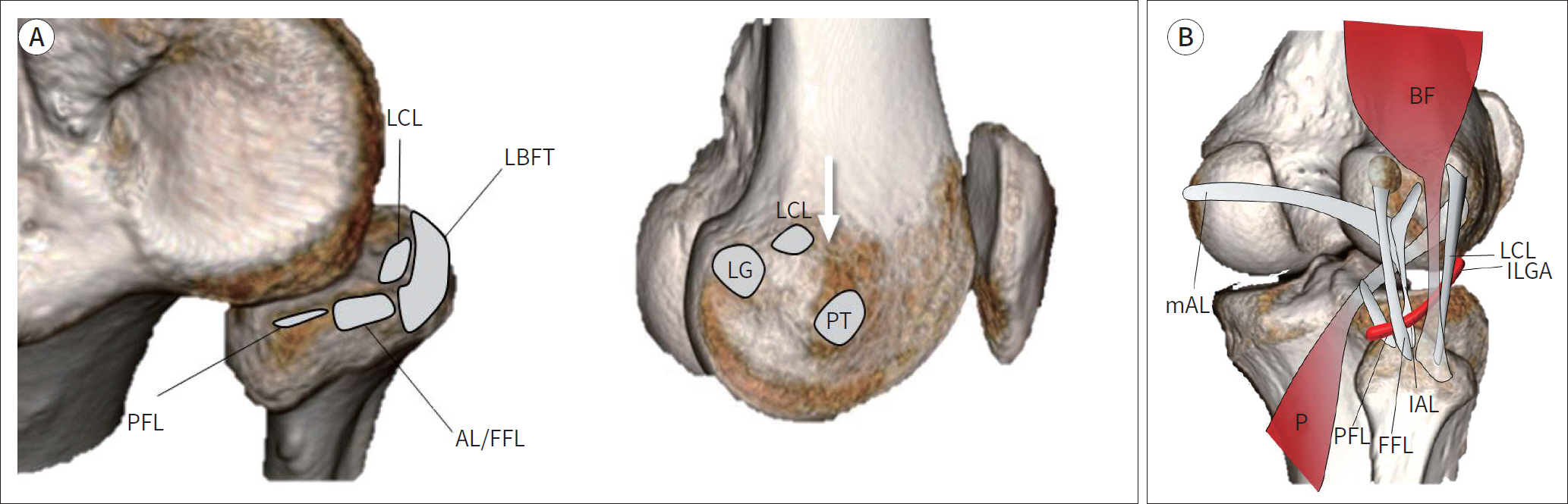
Fig. 1. Illustration demonstrating the normal anatomy of the posterolateral corner. A. Origins and insertion of posterolateral corner components. The LCL attaches centrally on the fibular head and is surrounded by the LBFT footprint. The AL and FFL attach to the fibular styloid process posteriorly and the PFL attaches medial to the attachment of the AL and FFL (left image). On the lateral surface of the lateral femoral condyle, the LCL originates posterior to the lateral femoral epicondyle (arrow) and anterior to the lateral head of gastrocnemius tendon (LG). Whereas the PT originates inferior and slightly anterior to the lateral epicondyle (right image). B. Courses of posterolateral corner components. The ‘P’ begins at the lateral surface of the lateral femoral condyle and passes deep to the LCL and the BF. Subsequently, the popliteus tendon passes under the mAL and lAL, and the FFL. The PFL is attached to the myotendinous junction of popliteus tendon and anchors it onto the tip of the fibular styloid process. The ILGA passes between the AL and the FFL and is a land-mark used to distinguish between them. AL = arcuate ligament, BF = biceps femoris tendon, FFL = fabellofibular ligament, lAL = lateral limbs of the arcuate ligaments, ILGA = inferior lateral genicular artery, LBFT = long head of biceps femoris tendon, LCL = lateral collateral ligament, LG = lateral head of gastrocnemius tendon, mAL = medial, P = popliteus tendon, PFL = popliteofibular ligament, PT = popliteus tendon
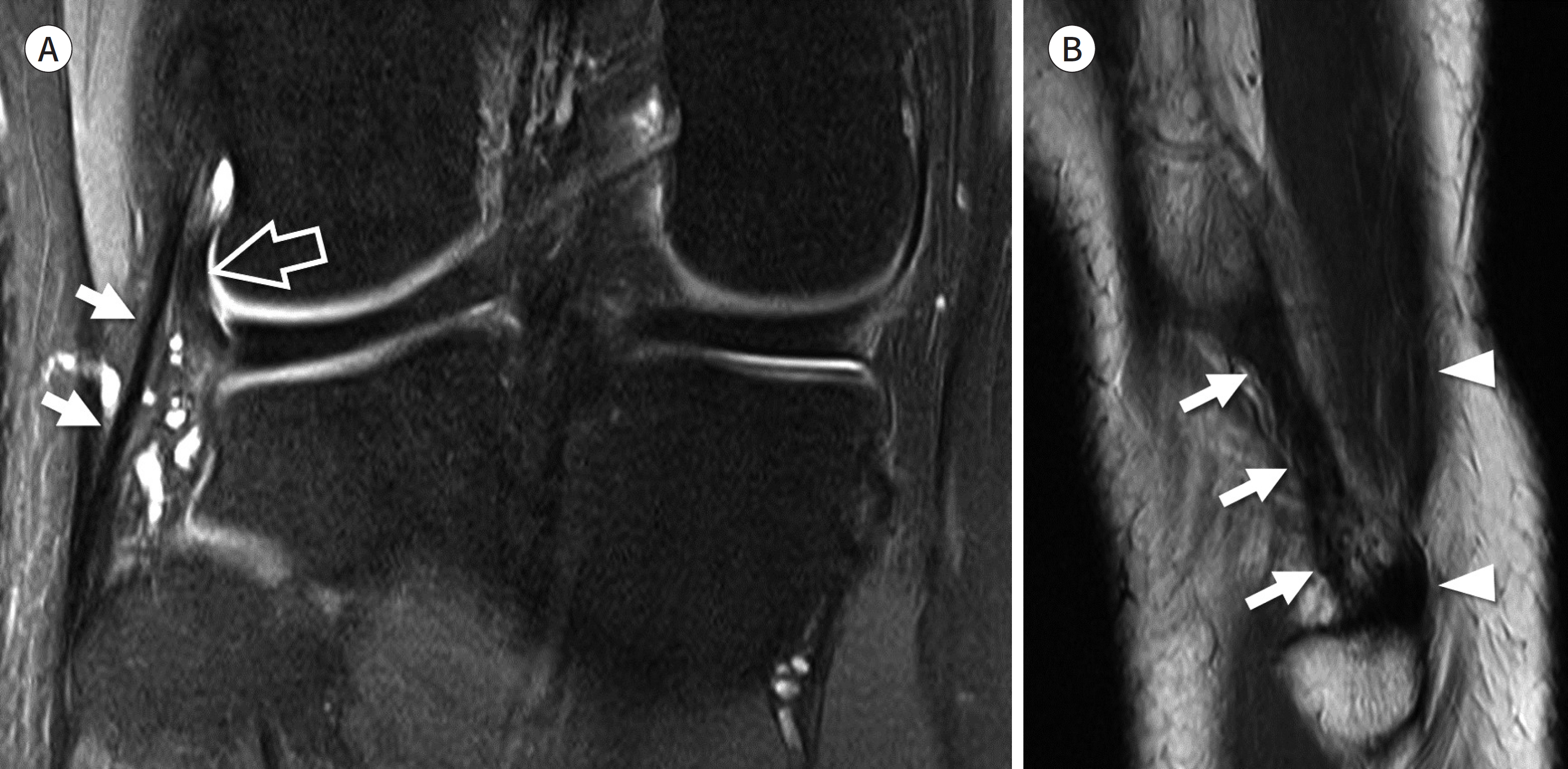
Fig. 2. Lateral collateral ligament. A. Coronal fat-suppressed intermediate-weighted image shows the entire course of the lateral collateral ligament (arrows) starting from the lateral femoral condyle to the fibular head. The intraarticular portion of the popliteus tendon (open arrow) located inner to lateral collateral ligament is also seen. B. Sagittal T2-weighted image of the lateral aspect of fibular head shows the lateral collateral ligament (arrows) and the biceps femoris tendon (arrowheads) which insert on the fibular head.
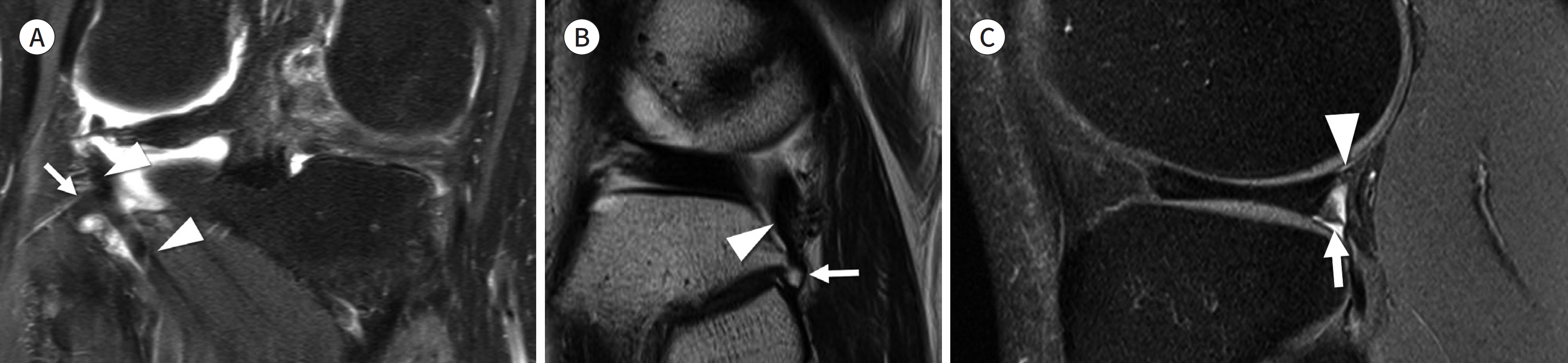
Fig. 3. Popliteofibular ligament and popliteomeniscal fascicle. A, B. Coronal fat-suppressed intermediate-weighted and sagittal T2-weighted images show the popliteofibular ligament (arrows) which attaches to the myotendinous junction of popliteus tendon (arrowheads). C. Sagittal fat-suppressed intermediate-weighted image shows the anteroinferior (arrow) and the posterosuperior (arrowhead) popliteomeniscal fascicles which connect the posterior horn of the lateral meniscus, the popliteus tendon, and the joint capsule.
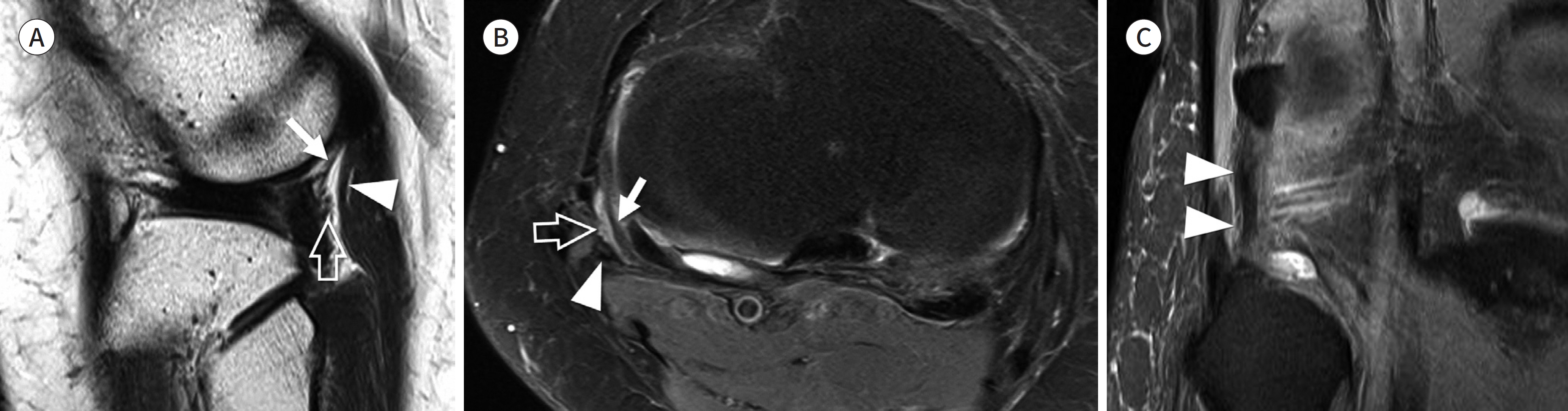
Fig. 4. Arcuate and fabellofibular ligament. A, B. Sagittal T2-weighted and axial fat suppressed intermediate weighted images show the lateral limb of arcuate ligament (arrows) and fabellofibular ligament (arrowheads). The inferior lateral genicular vessels (open arrows) pass between the arcuate ligament and the fabellofibular ligament (arrowheads). C. Coronal fat-suppressed intermediate-weighted image shows the fabellofibular ligament (arrowheads) which originates from the fabella and inserts onto the fibular styloid process immediately lateral to the popliteofibular ligament.
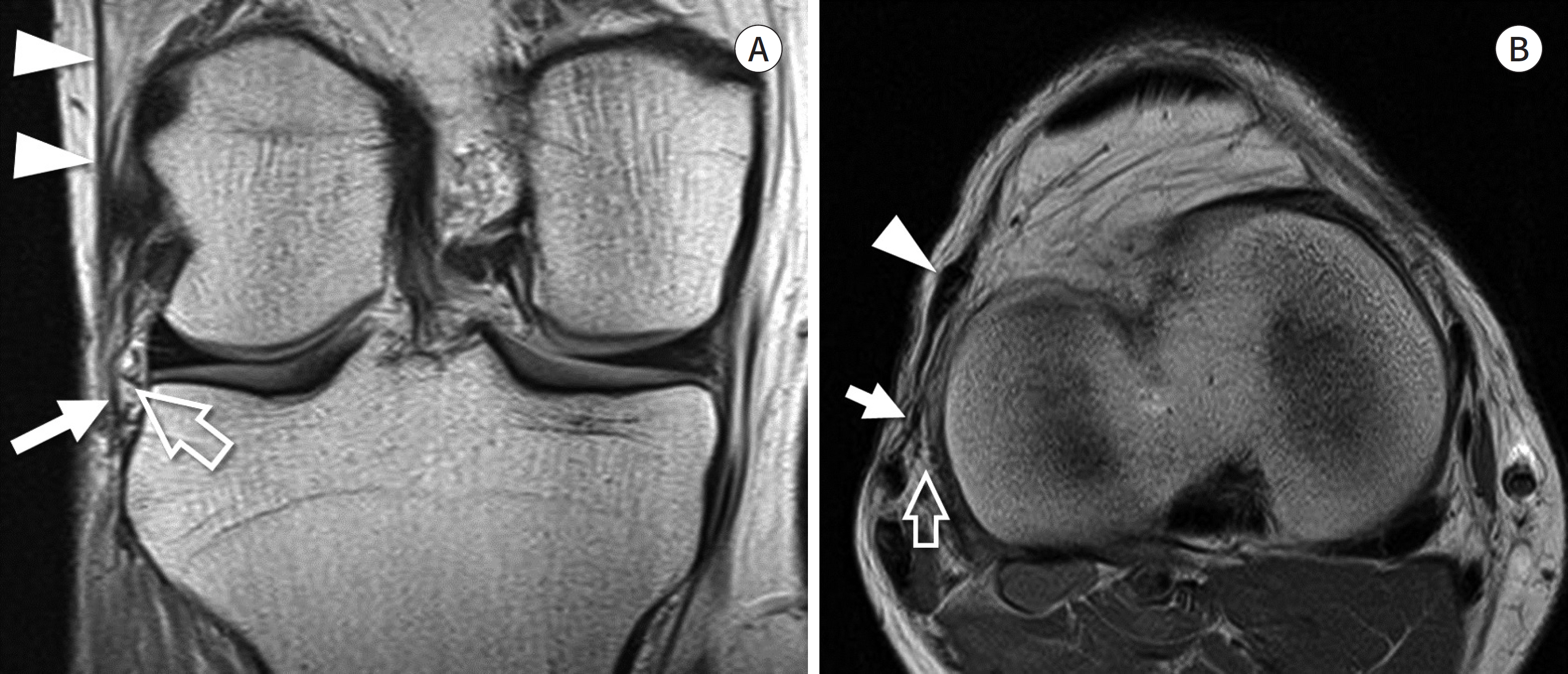
Fig. 5. Anterolateral ligament. A, B. Coronal and axial proton density weighted images demonstrate the capsulo-osseous layer of iliotibial band, also known as the anterolateral ligament (arrows), which courses lateral to the inferior lateral genicular vessel (open arrows) and finally inserts on the anterolateral tibial rim. The iliotibial band (arrowheads) courses anterior to the caspulo-osseous layer at the level of the joint and has a more anterior insertion on Gerdy's tubercle.
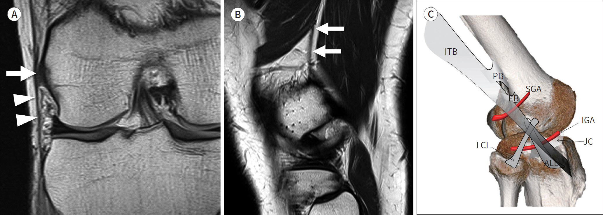
Fig. 6. Anterolateral ligament complex. A. Coronal proton density weighted image shows the epicondylar band (arrows) anchoring the iliotibial band (arrowheads) to the femur. B. Sagittal T2-weighted image demonstrates the proximal Kaplan fiber (arrows) of the iliotibial band attached to the linear aspera of the femoral shaft. C. Illustration depicting the anterolateral ligament complex. Sagittal diagram shows the ITB, the EB, the PB, the SGA, the IGA, the JC, the LCL, and the ALL. The epicondylar band and the proximal band of the ITB run from the ITB and insert on the lateral femoral condyle and the linear aspera, respectively. The ALL originates near the origin of the LCL. It passes above the inferior lateral genicular artery, connects to the joint capsule, and inserts on the tibia. ALL = anterolateral ligament, EB = epicondylar band, IGA = inferior lateral genicular artery, ITB = iliotibial band, JC = joint capsule, LCL = lateral collateral ligament, PB = proximal band of ITB, SGA = superior lateral genicular artery
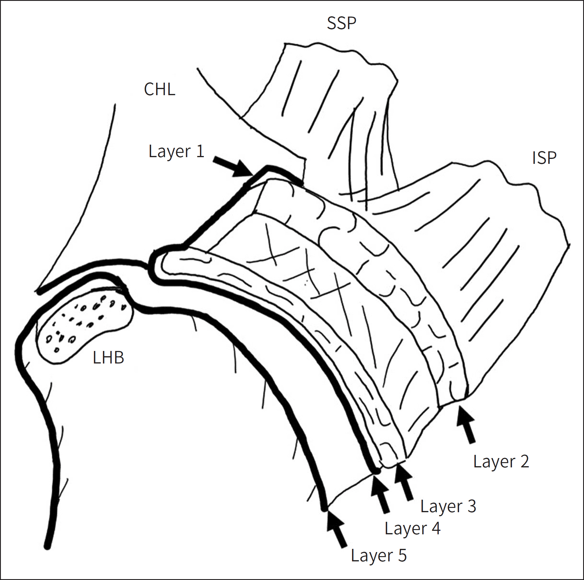
Fig. 7. Schematic diagram of a cross section through the SSP and the ISP tendons, parallel to the surface of the glenoid. Layer 1 is the most superficial, composed of fibers of the CHL extend-ing from the coracoid process to the greater tuberosity and overlies the cuff tendons. Layer 2 is composed of packed parallel tendon fibers ex-tending from the muscle belly of SSP and ISP to the humerus. Layer 3 has a tendinous structure with smaller fascicles compared to layer 2. The fibers of SSP in layer 3 are intermingled with fibers from the adjacent subscapularis and the ISP. Layer 4 is composed of loose connec-tive tissue having thick bands of collagen. Layer 5 is the deepest of all and forms the true joint capsule of the shoulder. CHL = coracohumeral ligament, ISP = infraspinatus, LHB = long head of biceps tendon, SSP = supraspinatus
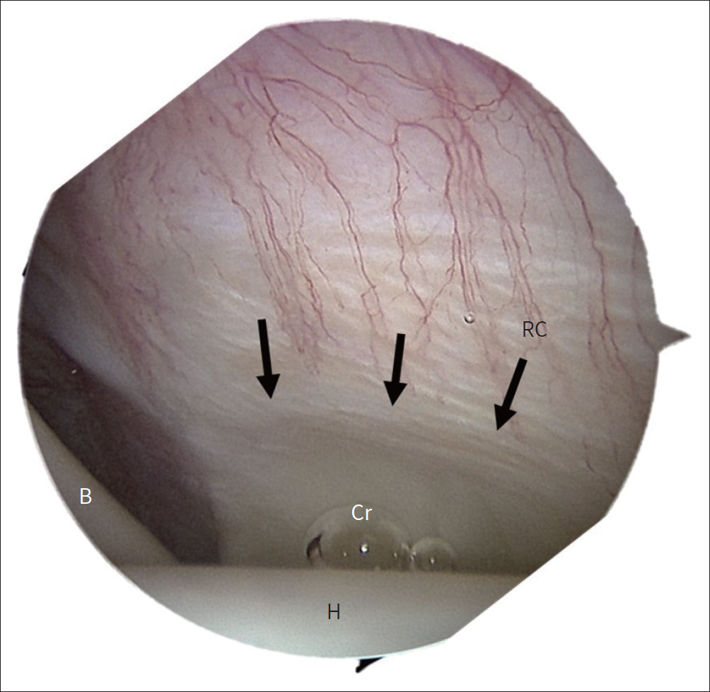
Fig. 8. Angled arthroscopic view of the humeral footprint of the supraspinatus shows the RC (arrows) and the Cr. Long head of the ‘B’ slides through the bicipital groove behind humeral ‘H.’ B = biceps tendon, Cr = crescent, H = head, RC = rotator cable
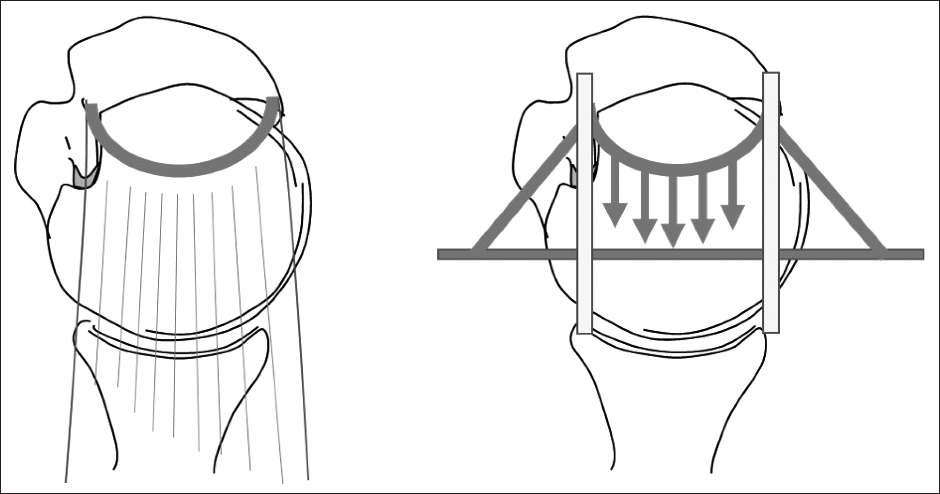
Fig. 9. “Suspension bridge model”. Osseous attachment of the rotator cable is analogous to the pillars of a suspension bridge, and the rotator cable is analogous to the cable connecting the pillars. The tension generated by the rotator cuff tendon medial to the cable is transferred to the osseous attachment, thereby preserving the function of the tendon as well as limiting the progression of a tear (Reference 31).
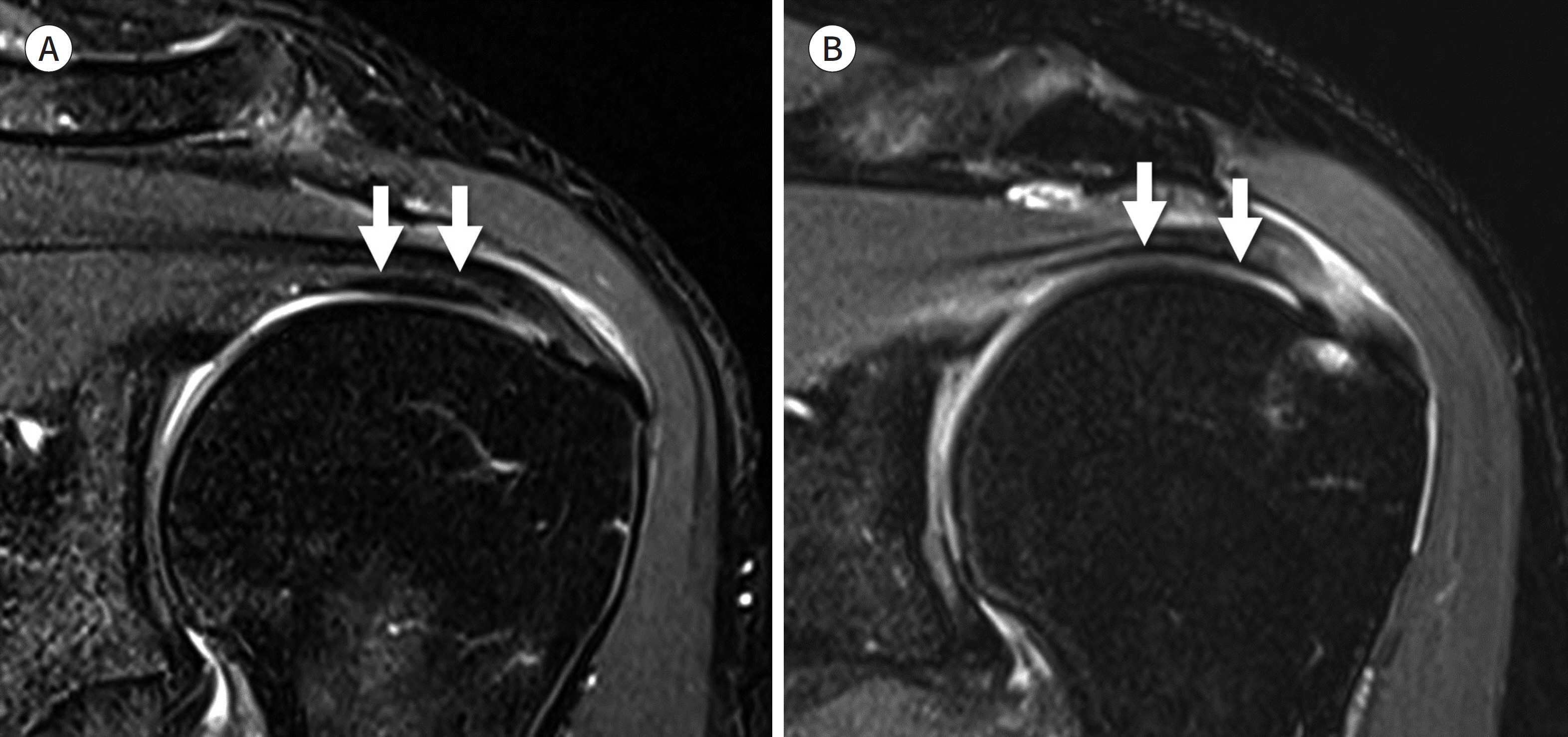
Fig. 10. Rotator cable. A. Oblique coronal T2-weighted image demonstrates the prominent rotator cable (arrows) on the articular side of the supraspinatus tendon, also referred to as the “cable-dominant rotator cuff.” B. Oblique coronal T2-weighted image demonstrates the superior capsule (arrows) on the articular side of the supraspinatus tendon devoid of a cable-like structure.
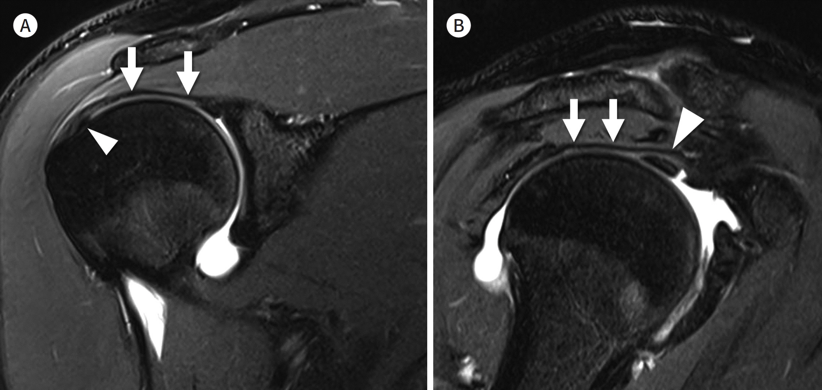
Fig. 11. Superior capsule of shoulder. A. Oblique coronal T2-weighted MR arthrography shows the superior capsule (arrows) and its footprint (arrowhead) on the greater tuberosity. B. Oblique sagittal T2-weighted MR arthrography shows the superior capsule (arrows) in continuum with the coracohumeral ligament (arrowhead).
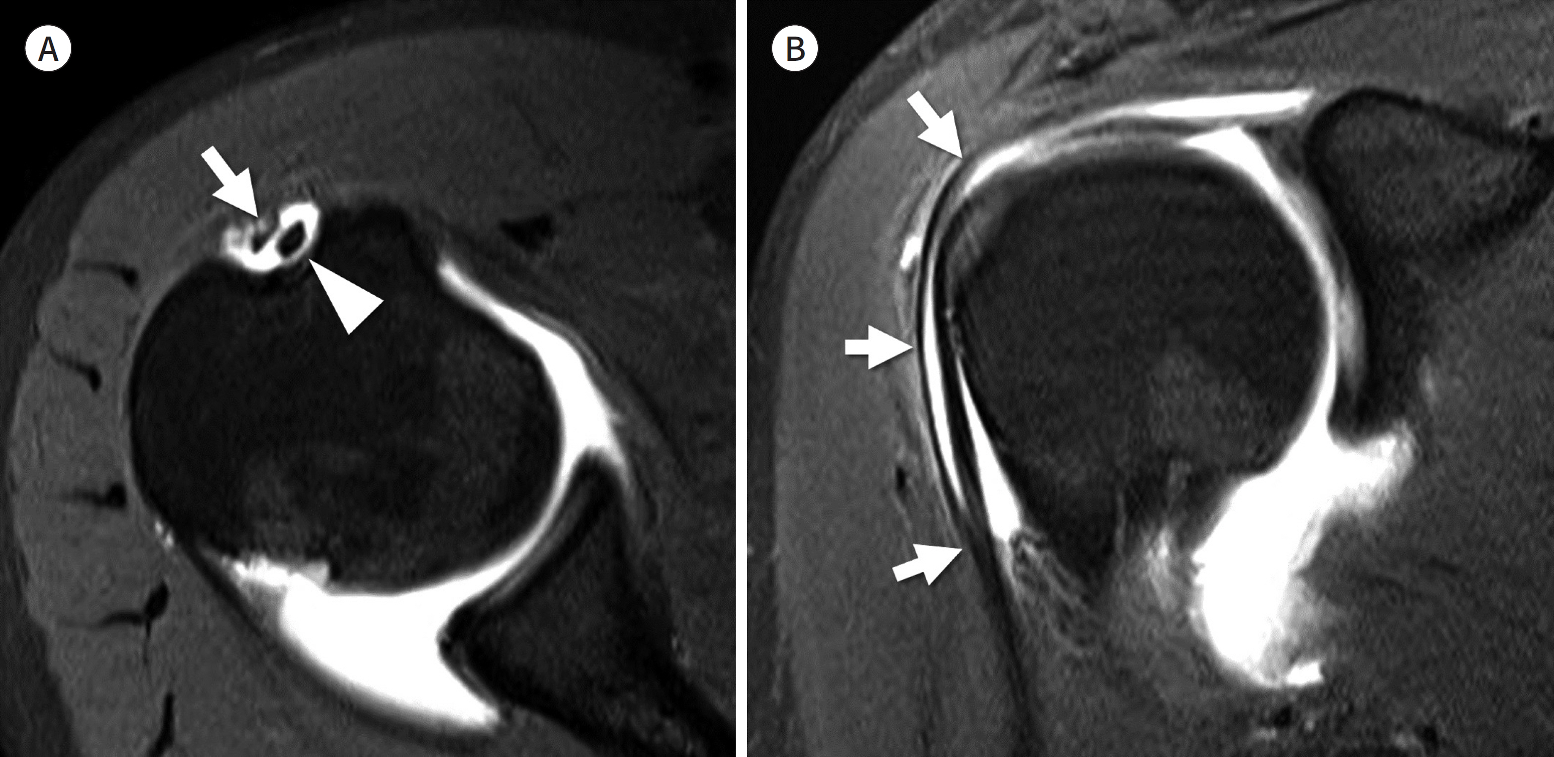
Fig. 12. Supraspinatus tendon slip. A. Axial T2-weighted MR arthrography shows the supraspinatus tendon slip (arrow) in the bicipital groove lateral to the long head of the biceps tendon (arrowhead). B. Oblique sagittal T2-weighted MR arthrography shows the course of the supraspinatus tendon slip (arrows) which originates from anterior margin of the supraspinatus and attaches to the humerus adjacent to the pectoralis major tendon.
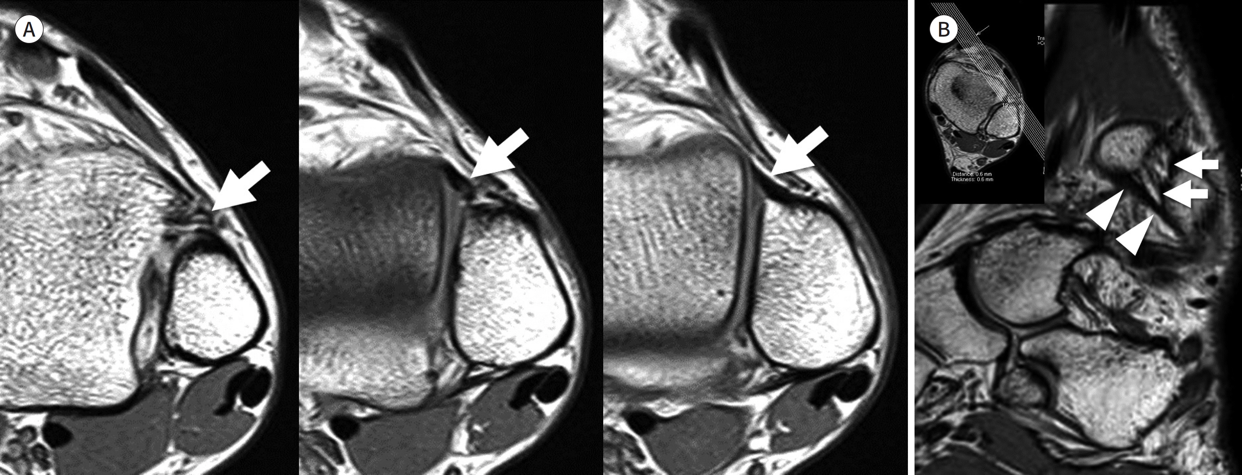
Fig. 13. Anteroinferior tibiofibular ligament. A. Consecutive axial T2-weighted images show obliquely oriented anteroinferior tibiofibular ligament (arrows) with origin at the tibia (left) and a fibular insertion (right). B. Oblique coronal reformatted three-dimensional fast spin-echo T2-weighted image shows the entire course of the anteroinferior fibular ligament (arrows) which is composed of multiple bundles. The inferior most bundle is the Basset's ligament (arrowheads).
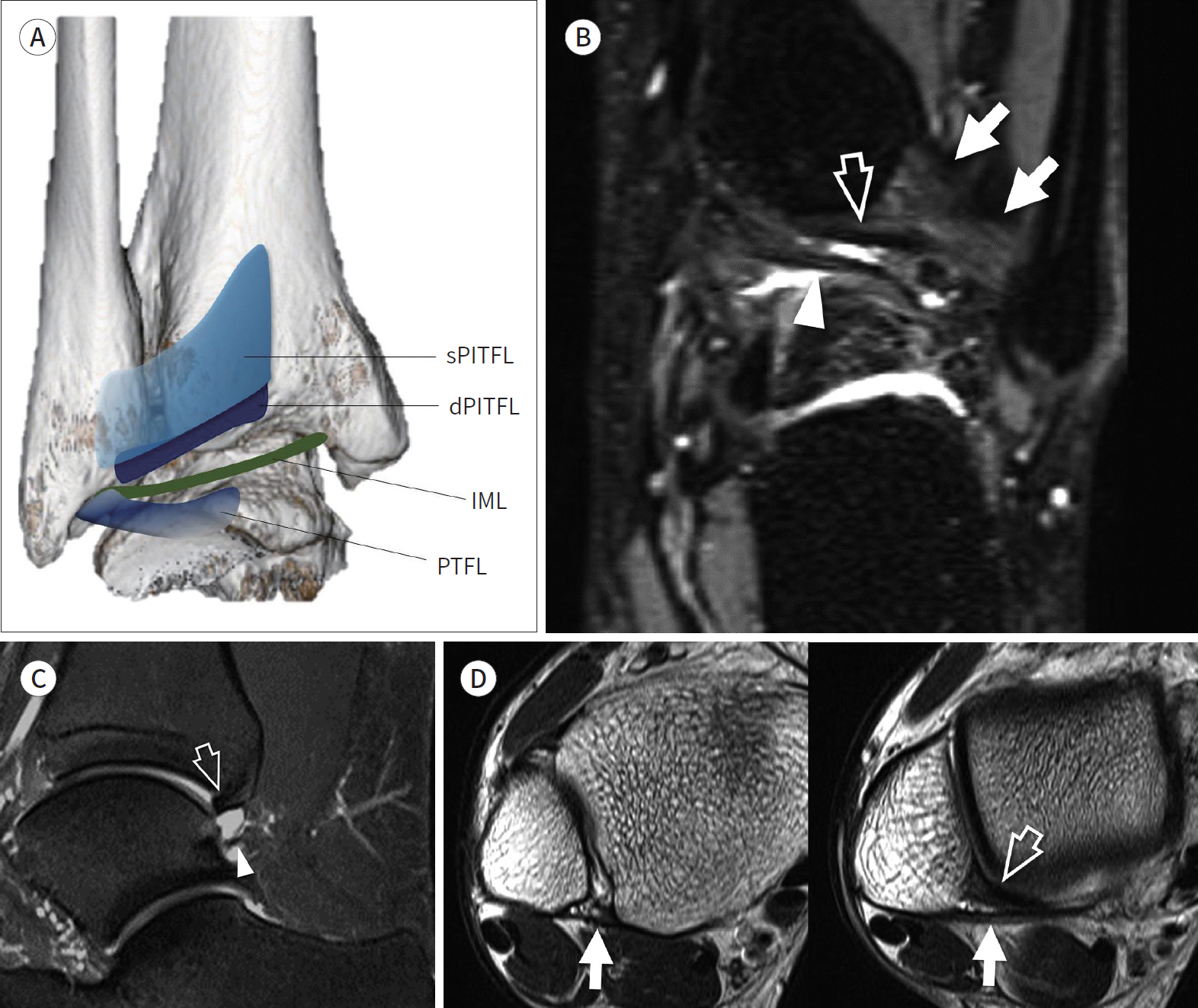
Fig. 14. Posteroinferior tibiofibular ligament complex. A. PITFL complex. The wide sPITFL originates from the posterior tubercle of the tibia and inserts on the posterior tubercle of the fibula. The dPITFL originates immediately inferior to the sPITFL and inserts on the posterior tubercle, deeper to the sPTIFL. The IML connects the inner surface of the medial malleolus and the lateral malleolus where the PTFL originates. B. Coronal fat-suppressed three-dimensional fast-spin echo sequence demonstrates the superficial PITFL (arrows), the dPITFL (open arrow), and the IML (arrowhead). C. Sagittal fat-suppressed intermediate-weighted image demonstrates the dPITFL (open arrow) which ap-pears like a “labrum” of the tibial rim, and the IML (arrowhead) which restricts the expansion of the posterior recess of the ankle. D. Axial T2-weighted images demonstrate the sPITFL (arrows) that originates from the posterior tubercle of tibia and inserts into posterior tubercle of fibula. The dPITFL (arrowhead) inserts deeper than the sPITFL into the posterior tubercle of the fibula. dPITFL = deep PITFL, IML = intermalleolar ligament, PITFL = posterior inferior tibiofibular ligament, PTFL = posterior talofibular ligament, sPITFL = superficial PITFL

Fig. 15. Interosseous membrane and interosseous ligament. A. Axial T2-weighted image shows the interosseous membrane (arrowhead) that connects the lateral margin of the tibia and the medial margin of the fibula. B, C. Coronal fat-suppressed T2-weighted and axial T2-weighted images show obliquely oriented interosseous ligament (arrows) composed of proximal and distal bands.
Reference
-
1. Rosas HG. Unraveling the posterolateral corner of the knee. Radiographics. 2016; 36:1776–1791.
Article2. DeLee JC, Riley MB, Rockwood CA Jr. Acute posterolateral rotatory instability of the knee.Am J Sports Med. 1983; 11:199–207.3. Hughston JC, Jacobson KE. Chronic posterolateral rotatory instability of the knee.J Bone Joint Surg Am. 1985; 67:351–359.4. Seebacher JR, Inglis AE, Marshall JL, Warren RF. The structure of the posterolateral aspect of the knee. J Bone Joint Surg Am. 1982; 64:536–541.
Article5. Bolog N, Hodler J. MR imaging of the posterolateral corner of the knee. Skeletal Radiol. 2007; 36:715–728.
Article6. Vinson EN, Major NM, Helms CA. The posterolateral corner of the knee. AJR Am J Roentgenol. 2008; 190:449–458.
Article7. Munshi M, Pretterklieber ML, Kwak S, Antonio GE, Trudell DJ, Resnick D. MR imaging, MR arthrography, and specimen correlation of the posterolateral corner of the knee: an anatomic study. AJR Am J Roentgenol. 2003; 180:1095–1101.8. Brinkman JM, Schwering PJ, Blankevoort L, Kooloos JG, Luites J, Wymenga AB. The insertion geometry of the posterolateral corner of the knee.J Bone Joint Surg Br. 2005; 87:1364–1368.9. De Maeseneer M, Shahabpour M, Vanderdood K, De Ridder F, Van Roy F, Osteaux M. Posterolateral support-ing structures of the knee: findings on anatomic dissection, anatomic slices and MR images.Eur Radiol. 2001; 11:2170–2177.10. Davies H, Unwin A, Aichroth P. The posterolateral corner of the knee. Anatomy, biomechanics and management of injuries. Injury. 2004; 35:68–75.11. Gollehon DL, Torzilli PA, Warren RF. The role of the posterolateral and cruciate ligaments in the stability of the human knee. A biomechanical study.J Bone Joint Surg Am. 1987; 69:233–242.12. Lee J, Papakonstantinou O, Brookenthal KR, Trudell D, Resnick DL. Arcuate sign of posterolateral knee injuries: anatomic, radiographic, and MR imaging data related to patterns of injury. Skeletal Radiol. 2003; 32:619–627.
Article13. Stäubli HU, Birrer S. The popliteus tendon and its fascicles at the popliteal hiatus: gross anatomy and functional arthroscopic evaluation with and without anterior cruciate ligament deficiency.Arthroscopy. 1990; 6:209–220.14. De Smet AA, Asinger DA, Johnson RL. Abnormal superior popliteomeniscal fascicle and posterior pericap-sular edema: indirect MR imaging signs of a lateral meniscal tear. AJR Am J Roentgenol. 2001; 176:63–66.15. Filli L, Rosskopf AB, Sutter R, Fucentese SF, Pfirrmann CWA. MRI predictors of posterolateral corner instability: a decision tree analysis of patients with acute anterior cruciate ligament tear. Radiology. 2018; 289:170–180.16. Diamantopoulos A, Tokis A, Tzurbakis M, Patsopoulos I, Georgoulis A. The posterolateral corner of the knee: evaluation under microsurgical dissection.Arthroscopy. 2005; 21:826–833.17. Covey DC. Injuries of the posterolateral corner of the knee.J Bone Joint Surg Am. 2001; 83:106–118.18. LaPrade RF, Resig S, Wentorf F, Lewis JL. The effects of grade III posterolateral knee complex injuries on anterior cruciate ligament graft force. A biomechanical analysis.Am J Sports Med. 1999; 27:469–475.
Article19. Segond P. Recherches cliniques et expérimentales sur les épanchements sanguins du genou par entorse. Paris: Aux Bureaux du Progrès médical;1879. p. 297–299.20. Vieira EL, Vieira EA, Da Silva RT, Berlfein PA, Abdalla RJ, Cohen M. An anatomic study of the iliotibial tract.Arthroscopy. 2007; 23:269–274.21. Hughston JC, Andrews JR, Cross MJ, Moschi A. Classification of knee ligament instabilities. Part II. The lateral compartment. J Bone Joint Surg Am. 1976; 58:173–179.
Article22. Van der Watt L, Khan M, Rothrauff BB, Ayeni OR, Musahl V, Getgood A, et al. The structure and function of the anterolateral ligament of the knee: a systematic review. Arthroscopy. 2015; 31:569–582.e3.
Article23. Herbst E, Albers M, Burnham JM, Fu FH, Musahl V. The anterolateral complex of the knee.Orthop J Sports Med. 2017; 5:2325967117730805.24. Coquart B, Le Corroller T, Laurent PE, Ollivier M, Pradel V, Champsaur P, et al. Anterolateral ligament of the knee: myth or reality?Surg Radiol Anat. 2016; 38:955–962.25. Helito CP, Helito PV, Costa HP, Bordalo-Rodrigues M, Pecora JR, Camanho GL, et al. MRI evaluation of the anterolateral ligament of the knee: assessment in routine 1.5-T scans.Skeletal Radiol. 2014; 43:1421–1427.26. Claes S, Bartholomeeusen S, Bellemans J. High prevalence of anterolateral ligament abnormalities in magnetic resonance images of anterior cruciate ligament-injured knees.Acta Orthop Belg. 2014; 80:45–49.27. Levy BA, Sabbag OD. Editorial commentary: is anterolateral ligament reconstruction of the knee needed? The debate rages on.Arthroscopy. 2017; 33:1584–1586.28. Kaplan EB. The iliotibial tract; clinical and morphological significance.J Bone Joint Surg Am. 1958; 40:817–832.29. Khanna M, Gupte C, Dodds A, Williams A, Walker M. Magnetic resonance imaging appearances of the capsu-lo-osseous layer of the iliotibial band and femoral attachments of the iliotibial band in the normal and piv-ot-shift ACL injured knee.Skeletal Radiol. 2019; 48:729–740.30. Clark JM, Harryman DT 2nd. Tendons, ligaments, and capsule of the rotator cuff. Gross and microscopic anatomy. J Bone Joint Surg Am. 1992; 74:713–725.
Article31. Burkhart SS, Esch JC, Jolson RS. The rotator crescent and rotator cable: an anatomic description of the shoulder's “suspension bridge.”Arthroscopy. 1993; 9:611–616.32. Burkhart SS. Fluoroscopic comparison of kinematic patterns in massive rotator cuff tears. A suspension bridge model.Clin Orthop Relat Res. 1992; 284:144–152.
Article33. Mesiha MM, Derwin KA, Sibole SC, Erdemir A, McCarron JA. The biomechanical relevance of anterior rotator cuff cable tears in a cadaveric shoulder model. J Bone Joint Surg Am. 2013; 95:1817–1824.
Article34. Morag Y, Jacobson JA, Lucas D, Miller B, Brigido MK, Jamadar DA. US appearance of the rotator cable with histologic correlation: preliminary results. Radiology. 2006; 241:485–491.
Article35. Choo HJ, Lee SJ, Kim DW, Park YM, Kim JH. Assessment of the rotator cable in various rotator cuff condi-tions using indirect MR arthrography.Acta Radiol. 2014; 55:1104–1111.36. Gyftopoulos S, Bencardino J, Nevsky G, Hall G, Soofi Y, Desai P, et al. Rotator cable: MRI study of its appearance in the intact rotator cuff with anatomic and histologic correlation.AJR Am J Roentgenol. 2013; 200:1101–1105.37. Podgórski MT, Olewnik L, Grzelak P, Polguj M, Topol M. Rotator cable in pathological shoulders: comparison with normal anatomy in a cadaveric study.Anat Sci Int. 2019; 94:53–57.38. Adams CR, DeMartino AM, Rego G, Denard PJ, Burkhart SS. The rotator cuff and the superior capsule: why we need both.Arthroscopy. 2016; 32:2628–2637.39. Mihata T, Lee TQ, Watanabe C, Fukunishi K, Ohue M, Tsujimura T, et al. Clinical results of arthroscopic superior capsule reconstruction for irreparable rotator cuff tears.Arthroscopy. 2013; 29:459–470.40. Adams CR, Denard PJ, Brady PC, Hartzler RU, Burkhart SS. The arthroscopic superior capsular reconstruction. Am J Orthop (Belle Mead NJ). 2016; 45:320–324.41. Clark J, Sidles JA, Matsen FA. The relationship of the glenohumeral joint capsule to the rotator cuff.Clin Orthop Relat Res. 1990; 254:29–34.42. Yuri T, Kobayashi H, Takano Y, Yoshida S, Naito A, Fujii H, et al. Capsular attachment of the subregions of rotator cuff muscles.Surg Radiol Anat. 2019; 41:1351–1359.43. Nimura A, Kato A, Yamaguchi K, Mochizuki T, Okawa A, Sugaya H, et al. The superior capsule of the shoulder joint complements the insertion of the rotator cuff.J Shoulder Elbow Surg. 2012; 21:867–872.44. Gheno R, Zoner CS, Buck FM, Nico MA, Haghighi P, Trudell DJ, et al. Accessory head of biceps brachii muscle: anatomy, histology, and MRI in cadavers. AJR Am J Roentgenol. 2010; 194:W80–W83.
Article45. Brodie CG. Note on the transverse-humeral, coraco-acromial, and coracohumeral ligaments, &c. J Anat Physiol. 1890; 24:247–252.46. Moser TP, Cardinal É, Bureau NJ, Guillin R, Lanneville P, Grabs D. The aponeurotic expansion of the supraspinatus tendon: anatomy and prevalence in a series of 150 shoulder MRIs.Skeletal Radiol. 2015; 44:223–231.47. Ramsey PL, Hamilton W. Changes in tibiotalar area of contact caused by lateral talar shift.J Bone Joint Surg Am. 1976; 58:356–357.48. Harris J, Fallat L. Effects of isolated Weber B fibular fractures on the tibiotalar contact area.J Foot Ankle Surg. 2004; 43:3–9.49. Hermans JJ, Beumer A, De Jong TA, Kleinrensink GJ. Anatomy of the distal tibiofibular syndesmosis in adults: a pictorial essay with a multimodality approach.J Anat. 2010; 217:633–645.50. Ogilvie-Harris DJ, Reed SC, Hedman TP. Disruption of the ankle syndesmosis: biomechanical study of the ligamentous restraints. Arthroscopy. 1994; 10:558–560.
Article51. Sarsam IM, Hughes SP. The role of the anterior tibiofibular ligament in talar rotation: an anatomical study. Injury. 1988; 19:62–64.
Article52. Kelikian H, Kelikian AS. Disorders of the ankle. Philadelphia: WB Saunders Company;1985. p. 4–8.53. Bartonícek J. Anatomy of the tibiofibular syndesmosis and its clinical relevance.Surg Radiol Anat. 2003; 25:379–386.54. Bassett FH 3rd, Gates HS 3rd, Billys JB, Morris HB, Nikolaou PK. Talar impingement by the anteroinferior tibiofibular ligament. A cause of chronic pain in the ankle after inversion sprain.J Bone Joint Surg Am. 1990; 72:55–59.55. Subhas N, Vinson EN, Cothran RL, Santangelo JR, Nunley JA 2nd, Helms CA. MRI appearance of surgically proven abnormal accessory anterior-inferior tibiofibular ligament (Bassett's ligament).Skeletal Radiol. 2008; 37:27–33.56. Akseki D, Pinar H, Yaldiz K, Akseki N, Arman C. The anterior inferior tibiofibular ligament and talar impingement: a cadaveric study.Knee Surg Sports Traumatol Arthrosc. 2002; 10:321–326.57. Akseki D, Pinar H, Bozkurt M, Yaldiz K, Araç S. The distal fascicle of the anterior inferior tibiofibular ligament as a cause of anterolateral ankle impingement: results of arthroscopic resection. Acta Orthop Scand. 1999; 70:478–482.
Article58. Jayatilaka MLT, Philpott MDG, Fisher A, Fisher L, Molloy A, Mason L. Anatomy of the insertion of the posterior inferior tibiofibular ligament and the posterior malleolar fracture. Foot Ankle Int. 2019; 40:1319–1324.
Article59. Norkus SA, Floyd RT. The anatomy and mechanisms of syndesmotic ankle sprains. J Athl Train. 2001; 36:68–73.60. Grath GB. Widening of the ankle mortise: a clinical and experimental study. Acta Chir Scand Suppl. 1960; (Suppl 263):1–88.61. Boonthathip M, Chen L, Trudell DJ, Resnick DL. Tibiofibular syndesmotic ligaments: MR arthrography in cadavers with anatomic correlation. Radiology. 2010; 254:827–836.
Article
- Full Text Links
-
- Actions
-
Cited
- CITED
-
- Close
- Share
-
- Similar articles
-
- Optimization of MRI Protocol for the Musculoskeletal System
- Easy Way Out-Quick Interpretation of Musculoskeletal Radiographs: The Lower Extremity
- New Technologies for Magnetic Resonance Imaging Compatible Device of Boston Scientific
- Drawing method can improve musculoskeletal anatomy comprehension in medical faculty student
- Normal Anatomy of Cranial Nerves III–XII on Magnetic Resonance Imaging
