Effect of prosthetic designs and alveolar bone conditions on stress distribution in fixed partial dentures with pier abutments
- Affiliations
-
- 1Department of Prosthodontics, College of Dentistry, Pusan National University, Korea. jeonyc@paran.com
Abstract
- STATEMENT OF PROBLEM: Pier abutments act as a Class I fulcrum lever system when the teeth are incorporated in a fixed partial denture with rigid connectors. Therefore non-rigid connector incorporated into the fixed partial denture might reduce the stresses created by the leverage. PURPOSE: The purpose of this study was to evaluate, by means of finite element method, the effects of non-rigid connectors and supporting alveolar bone level on stress distribution for fixed partial dentures with pier abutments. MATERIAL AND METHODS: A 2-dimensional finite element model simulating a 5-unit metal ceramic fixed partial denture with a pier abutment with rigid or non-rigid designs, the connector was located at the distal region of the second premolar, was developed. In the model, the lower canine, second premolar, and second molar served as abutments. Four types of alveolar bone condition were employed. One was normal bone condition and others were supporting bone reduced 20% height at one abutment. Two different loading conditions, each 150 N on 1st premolar and 1st molar and 300N on 1st molar, were used. RESULTS: Two types of FPD were displaced apically. The amount of displacement decreased in an almost linear slope away from the loaded point. Non-rigid design tended to cause the higher stresses in supporting bone of premolar and molar abutments and the lower stresses in that of canine than rigid design. Alveolar bone loss increased the stresses in supporting bone of corresponding abutment. CONCLUSION: Careful evaluation of the retentive capacity of retainers and the periodontal condition of abutments may be required for the prosthetic design of fixed partial denture with a pier abutment.
Keyword
MeSH Terms
Figure
-
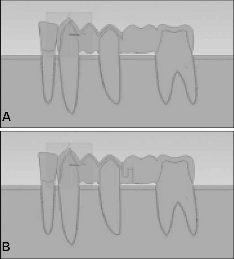
Fig. 1. Experimental models of 5-unit fixed partial denture (FPD). A, One-piece FPD. B, Nonrigid FPD with attachment.
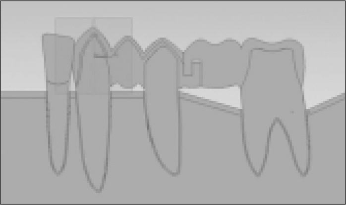
Fig. 2. Experimental model representing alveolar bone resorption of second molar.
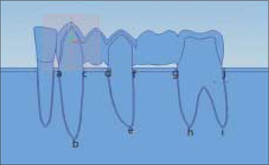
Fig. 3. Reference points for the comparison of stress distribution in supporting bone. A small letter a, c, d, f, g, j represent cervical portion of teeth and b, e, h, i represent root apex area of teeth.

Fig. 4. Displacement of experimental models. A, One-piece FPD loaded on first molar area. B, Non-rigid FPD loaded on first molar area. Black line represents the initial position of the model.

Fig. 5. von Mises stress distribution within FPD of experimental models with alveolar bone resorption of the second molar abutment. A and C, One-piece FPD. B and D, Non-rigid FPD. Arrows indicate the loading points.
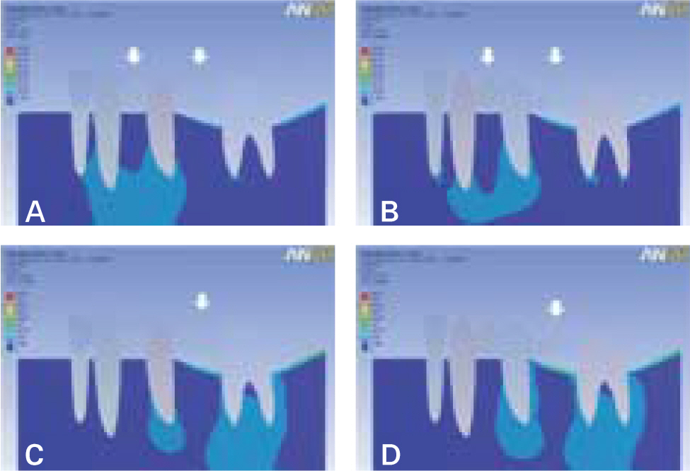
Fig. 6. von Mises stress distribution within supporting bone of experimental models with alveolar bone resorption of the second molar abutment. A and C, One-piece FPD. B and D, Non-rigid FPD. Arrows indicate the loading points.
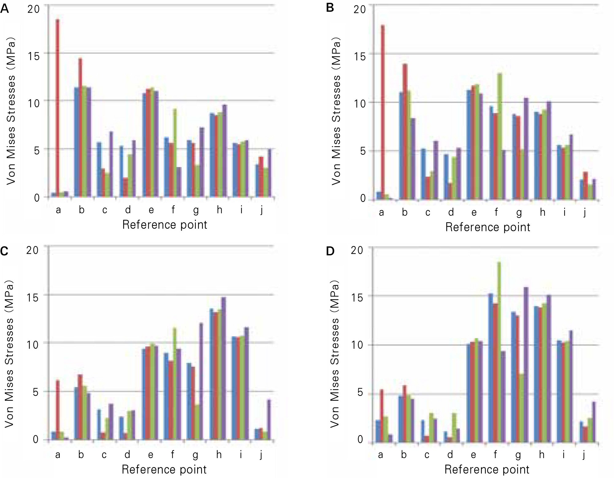
Fig. 7. von Mises stresses of reference points within supporting bone. (, Normal bone level., Alveolar bone resorption in canine., Alveolar bone resorption in second premolar., Alveolar bone resorption in second molar.) A, One-piece FPD loaded on first premolar and first molar. B, Non-rigid FPD loaded on first premolar and first molar. C, One-piece FPD loaded on first molar. D, Non-rigid FPD loaded on first molar.
Reference
-
1.Landry KE., Johnson PF., Parks VJ., Pelleu GB Jr. A photoelastic study to determine the location of the nonrigid connector in a five-unit intermediate abutment prosthesis. J Prosthet Dent. 1987. 57:454–7.
Article2.Standlee JP., Caputo AA. Load transfer by fixed partial dentures with three abutments. Quintessence Int. 1988. 19:403–10.3.Savion I., Saucier CL., Rues S., Sadan A., Blatz M. The pier abutment: a review of the literature and a suggested mathematical model. Quintessence Int. 2006. 37:345–52.4.Shillingburg HT Jr., Fisher DW. Nonrigid connectors for fixed partial dentures. J Am Dent Assoc. 1973. 87:1195–9.
Article5.Shillingburg HT., Hobo S., Whitsett LD., Jacobi R., Brachett SE. Fundamentals of Fixed Rosthodontics. 3rd ed.Chicago: Quintessence Publishing Co, Inc.;1997. p. 85–118.6.Guichet NF. Occlusion-a teaching manual. Anaheim: Denar Co.;1970. p. 26.7.Markley MR. Broken-stress principle and design in fixed bridge prosthesis. J Prosthet Dent. 1951. 1:416–23.
Article8.Gill JR. Treatment planning for mouth rehabilitation. J Prosthet Dent. 1952. 2:230–45.
Article9.Adams JD. Planning posterior bridges. J Am Dent Assoc. 1956. 53:647–54.
Article10.Ferencz JL. The use of nonrigid connectors for long span ceramo-metal fixed partial dentures. N Y J Dent. 1978. 48:287–91.11.Botelho MG., Dyson JE. Long-span, fixed-movable, resin-bonded fixed partial dentures: a retrospective, preliminary clinical investigation. Int J Prosthodont. 2005. 18:371–6.12.Ziada HM., Orr JF., Benington IC. Photoelastic stress analysis in a pier retainer of an anterior resin-bonded fixed partial denture. J Prosthet Dent. 1998. 80:661–5.
Article13.Oruc S., Eraslan O., Tukay HA., Atay A. Stress analysis of effects of nonrigid connectors on fixed partial dentures with pier abutments. J Prosthet Dent. 2008. 99:185–92.
Article14.Son Ho., Kim YS., Kim EN., Kim JD., Kim CY., Na JS, et al. Dental anatomy. 5th ed.Jeesung Publishing Inc.;2001. p. 85–196.15.Wheeler RC. Dental Anatomy, Physiology and Occlusion. 5th ed.WB Saunders Co.;1974. p. 184–287.16.Carranza FA., Newman MG., Takei H., Klokkevold PR. Carranza' s clinical periodontology. 10th ed.St Louis: Saunders;2006. p. 68.17.Eraslan O., Sevimay M., Usumez A., Eskitascioglu G. Effects of cantilever design and material on stress distribution in fixed partial dentures—a finite element analysis. J Oral Rehabil. 2005. 32:273–8.18.Goel VK., Khera SC., Gurusami S., Chen RC. Effect of cavity depth on stresses in a restored tooth. J Prosthet Dent. 1992. 67:174–83.
Article19.Farah JW., Craig RG., Meroueh KA. Finite element analysis of three- and four-unit bridges. J Oral Rehabil. 1989. 16:603–11.
Article20.Morris HF. Veterans Administration Cooperative Studies Project No. 147/242. Part VII: The mechanical properties of metal ceramic alloys as cast and after simulated porcelain firing. J Prosthet Dent. 1989. 61:160–9.
Article21.Lee JH., Kim JS. Oral Physiology. 4th ed.Koonja Publishing Co.;1994. p. 121.22.Boucher CO., Zarb GA., Carlsson GE., Bolender CL. Boucher's Prosthodontic Treatment for Edentulous Patients. 11th ed.St. Louis: Elsevier;1997. p. 358–89.23.Farah JW., Craig RG. Reflection photoelastic stress analysis of a dental bridge. J Dent Res. 1971. 50:1253–9.
Article24.el-Ebrashi MK., Craig RG., Peyton FA. Experimental stress analysis of dental restorations. VII. Structural design and stress analysis of fixed partial dentures. J Prosthet Dent. 1970. 23:177–86.25.Sutherland JK., Holland GA., Sluder TB., White JT. A photoelastic analysis of the stress distribution in bone supporting fixed partial dentures of rigid and nonrigid design. J Prosthet Dent. 1980. 44:616–23.
Article26.Moulding MB., Holland GA., Sulik WD. Photoelastic stress analysis of supporting alveolar bone as modified by nonrigid connectors. J Prosthet Dent. 1988. 59:263–74.
Article
- Full Text Links
-
- Actions
-
Cited
- CITED
-
- Close
- Share
-
- Similar articles
-
- 3-D Finite element stress analysis in screw-type, cement-type, and combined-type implant fixed partial denture designs
- Strain on the labial plates around abutments supporting removable partial dentures with various prosthetic designs: an in vitro study
- Study of the fracture resistance of zirconia on posterior fixed partial dentures based on inter-abutment distance
- A photoelastic stress analysis of fixed partial dentures with bicon implants on mandibular posterior area
- Photoelastic stress analysis of implants according to fixture design
