Cortical bone thickness and root proximity at mandibular interradicular sites: implications for orthodontic mini-implant placement
- Affiliations
-
- 1Department of Orthodontics, Graduate School of Clinical Dentistry, Ewha Womans University, Korea. whlim@snu.ac.kr
- 2Department of Orthodontics, School of Dentistry, Seoul National University, Korea.
- KMID: 2273971
- DOI: http://doi.org/10.4041/kjod.2008.38.6.397
Abstract
OBJECTIVE
The purpose of this study was to provide clinical guidelines to indicate the best location for mini-implants as it relates to the cortical bone thickness and root proximity.
METHODS
CT images from 14 men and 14 women were used to evaluate the buccal interradicular cortical bone thickness and root proximity from mesial to the central incisor to the 2nd molar. Cortical bone thickness was measured at 4 different angles including 0degrees, 15degrees, 30degrees, and 45degrees.
RESULTS
There was a statistically significant difference in cortical bone thickness between the second premolar/ first permanent molar site, central incisor/central incisor site, between the first/second permanent molar site and in the anterior region. A statistically significant difference in cortical bone thickness was also found when the angulation of placement was increased except for the 2 mm level from the alveolar crest. Interradicular spaces at the 1st/2nd premolar, 2nd premolar/1st permanent molar and 1st/2nd permanent molar sites are considered to be wide enough for mini-implant placement without root damage.
CONCLUSIONS
Given the limits of this study, mini-implants for orthodontic anchorage may be well placed at the 4 and 6 mm level from the alveolar crest in the posterior region with a 30degrees and 45degrees angulation upon placement.
Figure
-

Fig 1 A, 3D reconstructed CT image using V-works 4.0™; B, bisect the image along a line that passes the contact point and perpendicular to the occlusal plane; C, bisected and 90° right-rotated sagittal image between Lt. and Rt. mandibular central incisors.
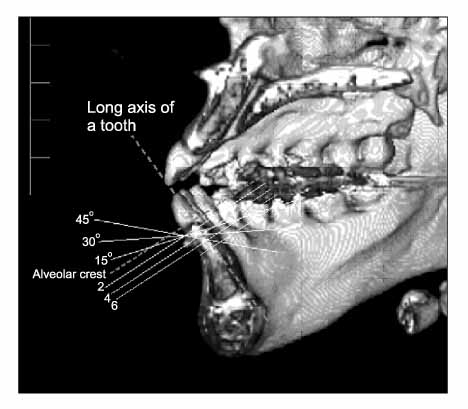
Fig 2 Measurement of cortical bone thickness. Cortical bone thickness was measured in 4 different angles (0°, 15°, 30°, 45°) at 2, 4, 6 mm height from the alveolar crest.
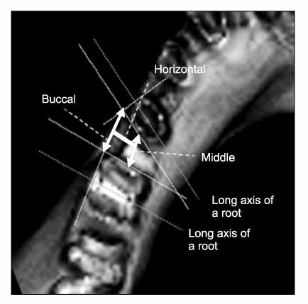
Fig 3 Measurement of root proximity. 'Central' means the closest distance between the tangent lines, each one tangent to the proximal root surface. 'Buccal' means the distance between the intersecting points which are made by two tangent lines, one is tangent to proximal root surface and the other is tangent to buccal root surface. 'Horizontal' means the closest distance from 'buccal' to 'central'.
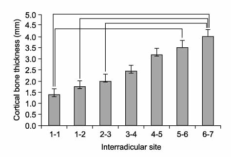
Fig 4 Mean value of cortical bone thickness in the mandible. Inter-bar connecting lines mean significant differences between one and the other (p < 0.05). 1, Central incisor; 2, lateral incisor; 3, canine; 4, first premolar; 5, second premolar; 6, first molar; 7, second molar.
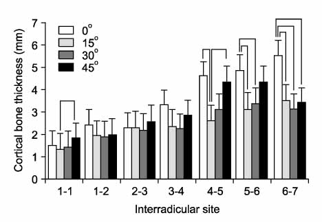
Fig 5 Cortical bone thickness with different angulations at the 2 mm level. Inter-bar connecting lines mean significant differences between one and the other (p < 0.05). 1, Central incisor; 2, lateral incisor; 3, canine; 4, first premolar; 5, second premolar; 6, first molar; 7, second molar.
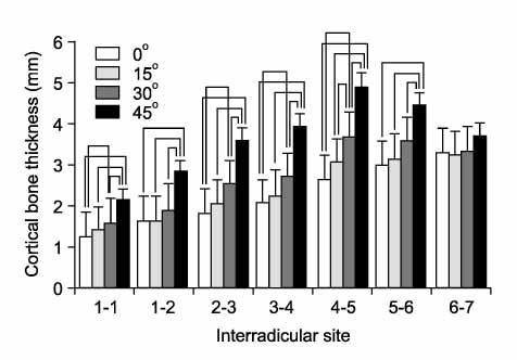
Fig 6 Cortical bone thickness with different angulations at the 4 mm level. Inter-bar connecting lines mean significant differences between one and the other (p < 0.05). 1, Central incisor; 2, lateral incisor; 3, canine; 4, first premolar; 5, second premolar; 6, first molar; 7, second molar.
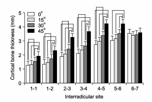
Fig 7 Cortical bone thickness with different angulations at the 6 mm level. Inter-bar connecting lines mean significant differences between one and the other (p < 0.05). 1, Central incisor; 2, lateral incisor; 3, canine; 4, first premolar; 5, second premolar; 6, first molar; 7, second molar.
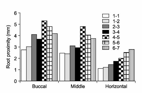
Fig 8 Mean value of root proximity in the mandible. 1, Central incisor; 2, lateral incisor; 3, canine; 4, first premolar; 5, second premolar; 6, first molar; 7, second molar.
Cited by 2 articles
-
Effects of orthodontic mini-implant position in the dragon helix appliance on tooth displacement and stress distribution: a three-dimensional finite element analysis
Min-Ji Kim, Sun-Hyung Park, Hyeon-Seong Kim, Sung-Seo Mo, Sang-Jin Sung, Gang-Won Jang, Youn-Sic Chun
Korean J Orthod. 2011;41(3):191-199. doi: 10.4041/kjod.2011.41.3.191.Evaluation of factors influencing the success rate of orthodontic microimplants using panoramic radiographs
Jae Hyun Park, Jong-Moon Chae, R. Curtis Bay, Mi-Jung Kim, Keun-Young Lee, Na-Young Chang
Korean J Orthod. 2018;48(1):30-38. doi: 10.4041/kjod.2018.48.1.30.
Reference
-
1. Kim HJ, Yun HS, Park HD, Kim DH, Park YC. Soft-tissue and cortical-bone thickness at orthodontic implant sites. Am J Orthod Dentofacial Orthop. 2006. 130:177–182.
Article2. Miyawaki S, Koyama I, Inoue M, Mishima K, Sugahara T, Takano-Yamamoto T. Factors associated with the stability of titanium screws placed in the posterior region for orthodontic anchorage. Am J Orthod Dentofacial Orthop. 2003. 124:373–378.
Article3. Deguchi T, Nasu M, Murakami K, Yabuuchi T, Kamioka H, Takano-Yamamoto T. Quantitative evaluation of cortical bone thickness with computed tomographic scanning for orthodontic implants. Am J Orthod Dentofacial Orthop. 2006. 129:721.
Article4. Kuroda S, Yamada K, Deguchi T, Hashimoto T, Kyung HM, Takano-Yamamoto T. Root proximity is a major factor for screw failure in orthodontic anchorage. Am J Orthod Dentofacial Orthop. 2007. 131:suppl. 68S–73S.
Article5. Roberts WE, Marshall KJ, Mozsary PG. Rigid endosseous implant utilized as anchorage to protract molars and close an atrophic extraction site. Angle Orthod. 1990. 60:135–152.6. Kang S, Lee SJ, Ahn SJ, Heo MS, Kim TW. Bone thickness of the palate for orthodontic mini-implant anchorage in adults. Am J Orthod Dentofacial Orthop. 2007. 131:suppl. 74S–81S.
Article7. Park YC, Kim JK, Lee JS. Atlas of contemporary orthodontics. 2005. Volume III:. Seoul: Shinheung international;1921–23. 145159178–187.8. Park HS. An anatomical study using CT images for the implantation of micro-implants. Korean J Orthod. 2002. 32:435–441.9. Kravitz ND, Kusnoto B. Risks and complications of orthodontic miniscrews. Am J Orthod Dentofacial Orthop. 2007. 131:suppl. 43S–51S.
Article10. Youn HK. Evaluation of interdental space of maxillary posterior area for orthodontic mini-implant using Cone beam CT [thesis]. 2006. Seoul: Catholic University of Korea.11. Kyung HM, Park HS, Bae SM, Sung JH, Kim IB. Development of orthodontic micro-implants for intraoral anchorage. J Clin Orthod. 2003. 37:321–328.12. Melsen B, Costa A. Immediate loading of implants used for orthodontic anchorage. Clin Orthod Res. 2000. 3:23–28.
Article13. Lee SK, Lim WH, Chun YS. Quantitative evaluation of cortical bone and soft tissue thickness in mandible. Korean J Orthod. 2007. 37:212–219.14. Park HS, Jeong SH, Kwon OW. Factors affecting the clinical success of screw implants used as orthodontic anchorage. Am J Orthod Dentofacial Orthop. 2006. 130:18–25.
Article15. Kuroda S, Sugawara Y, Deguchi T, Kyung HM, Takano-Yamamoto T. Clinical use of miniscrew implants as orthodontic anchorage: success rates and postoperative discomfort. Am J Orthod Dentofacial Orthop. 2007. 131:9–15.
Article16. Masumoto , Hayashi I, Kawamura A, Tanaka K, Kasai K. Relationships among facial type, buccolingual molar inclination, and cortical bone thickness of the mandible. Eur J Orthod. 2001. 23:15–23.
Article17. Costa A, Pasta G, Bergamaschi G. Intraoral hard and soft tissue depths for temporary anchorage devices. Semin Orthod. 2005. 11:10–15.
Article18. Lim WH, Lee SK, Wikesjö UM, Chun YS. A descriptive tissue evaluation at maxillary interradicular sites: implications for orthodontics mini-implant placement. Clin Anat. 2007. 20:760–765.
Article19. Periago DR, Scarfe WC, Moshiri M, Scheetz JP, Silveira AM, Farman AG. Linear accuracy and reliability of cone beam CT derived 3-dimensional images constructed using an orthodontic volumetric rendering program. Angle Orthod. 2008. 78:387–395.
Article20. Stratemann SA, Huang JC, Maki K, Miller AJ, Hatcher DC. Comparison of cone beam computed tomography imaging with physical measures. Dentomaxillofac Radiol. 2008. 37:80–93.
Article21. Suomalainen A, Vehmas T, Kortesniemi M, Robinson S, Peltola J. Accuracy of linear measurements using dental cone beam and conventional multislice computed tomography. Dentomaxillofac Radiol. 2008. 37:10–17.
Article22. Choi SC, Ann CH, Choi HM, Heo MS, Lee SS. Accuracy of reformatted CT image for measuring the pre-implant site: analysis of the image distortion related to the gantry angle change. Dentomaxillofac Radiol. 2002. 31:273–277.
Article
- Full Text Links
-
- Actions
-
Cited
- CITED
-
- Close
- Share
-
- Similar articles
-
- Restoration-oriented anatomical analysis of alveolar bone at mandibular first molars and implications for immediate implant placement surgery: a CBCT study
- Histomorphometric evaluation of the bone surrounding orthodontic miniscrews according to their adjacent root proximity
- Geometrical design characteristics of orthodontic mini-implants predicting maximum insertion torque
- Quantitative evaluation of cortical bone and soft tissue thickness in the mandible
- Buccal cortical bone thickness on CBCT for mini-implant
