Determining the Location of Metallic Needle from MR Images Distorted by Susceptibility Difference
- Affiliations
-
- 1Fusion Technology Medical Device Team, Korea Food & Drug Administration, Korea.
- 2Molecular Imaging and Therapy Branch, National Cancer Center, Korea. dkim@ncc.re.kr
- KMID: 2206905
- DOI: http://doi.org/10.13104/jksmrm.2010.14.2.87
Abstract
- PURPOSE
To calculate the appearance of the image distortion from metallic artifacts and to determine the location of a metallic needle from a distorted MR image.
MATERIALS AND METHODS
To examine metal artifacts, an infinite metal cylinder in a strong magnetic field are assumed. The cylinder's axis leaned toward the magnetic field along some arbitrary angle. The Laplace equation for this situation was solved to investigate the magnetic field distortion, and the simulation was performed to evaluation the image artifact caused by both readout and slice-selection gradient field. Using the result of the calculation, the exact locations of the metal cylinder were calculated from acquired images.
RESULTS
The distances between the center and the folded point are measured from images and calculated. Percentage errors between the measured and calculated distance were less than 5%, except for one case.
CONCLUSION
The simulation was successfully performed when the metal cylinder was skewed at an arbitrary tilted angle relative to the main magnetic field. This method will make it possible to monitor and guide both biopsy and surgery with real time MRI.
MeSH Terms
Figure
-
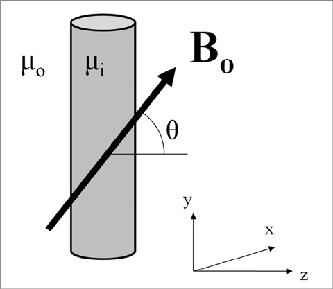
Fig. 1 An infinite metallic cylinder is put in a strong homogeneous magnetic field. The angle between the main magnetic field and the plane perpendicular to the metal cylinder is θ. The right hand coordinate system is used. The axis of the cylinder is parallel to y-axis and the main magnetic field Bo lies in y-z plane.

Fig. 2 Simulated slices were plotted with Mathematica. The tilted angle of the metal cylinder is 30°. (a). The distorted slice is selected by the slice selection gradient. The direction of the slice gradient is perpendicular to main magnetic field. (b). When the readout gradient is applied to the slice in (a), each pixel in the slice is shifted along the readout gradient direction. The direction of the readout gradient is parallel to the main magnetic field. (c). The top view of (b) is plotted where the point 'f' represents the folded point and 'p' represents the piled point.
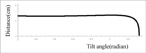
Fig. 3 The distance from the cylinder center to the folded point as a function of the metallic cylinder's tilt angle relative to the main magnetic field. X-axis is plotted versus radians. The distance was not proportional to the tilt angle.
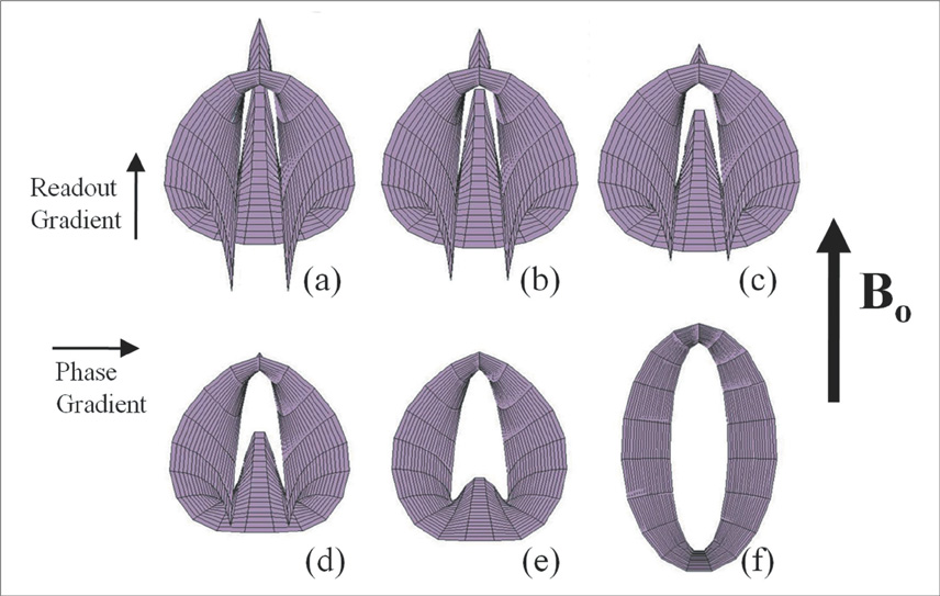
Fig. 4 Simulated slices are plotted for various tilt angles ((a)-(f)): 0°, 15°, 30°, 45°, 60°, and 75°. The shape of the magnetic field distortion varied as a function of tilt angle. Each slice was generated with the same parameters, except for the tilt angle.
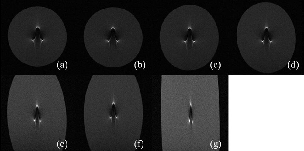
Fig. 5 Cross sectional images of the stainless steel cylindrical rod were acquired. Its diameter and length were 1 mm and 20 cm, respectively. The tilt angles (θ) measured during imaging were 0°, 8°, 24°, 32°, 56°, and 73°((a)-(g)), respectively. The readout gradient direction was top-to-bottom. The artifact shapes did not increase in size along the readout encoding direction, which is similar to the results shown in Fig. 4.
Reference
-
1. Lüdeke KM, Röschmann P, Tischler R. Susceptibility artefacts in NMR imaging. Magn Reson Imaging. 1985. 3:329–343.2. Schenck JF. The role of magnetic susceptibility in magnetic resonance imaging: MRI magnetic compatibility of the first and second kinds. Med Phys. 1996. 23:815–850.3. Butts K, Pauly JM, Daniel BL, Kee S, Norbash AM. Management of biopsy needle artifacts: techniques for RF-refocused MRI. J Magn Reson Imaging. 1999. 9:586–595.4. Cho ZH, Kim DJ, Kim YK. Total inhomogeneity correction including chemical shifts and susceptibility by view angle tilting. Med Phys. 1988. 15:7–11.5. Lu W, Pauly KB, Gold GE, Pauly JM, Hargreaves BA. SEMAC: Slice Encoding for Metal Artifact Correction in MRI. Magn Reson Med. 2009. 62:66–76.6. Arbogast-Ravier S, Gangi A, Choquet P, Brunot B, Constantinesco A. An in Vitro Study at Low Field for MR Guidance of a Biopsy Needle. Magn Reson Imaging. 1995. 13:321–324.7. Ladd ME, Erhart P, Debatin JF, Romanowski BJ, Boesiger P, McKinnon GC. Biopsy needle susceptibility artifacts. Magn Reson Med. 1996. 36:646–651.8. Lufkin R, Teresi L, Hanafee W. New Needle for MR-Guided Aspiration Cytology of the Head and Neck. AJR Am J Roentgenol. 1987. 149:380–382.9. Lufkin R, Teresi L, Chiu L, Hanafee W. A Technique for MR-Guided Needle Placement. AJR Am J Roentgenol. 1988. 151:193–196.10. Liu H, Martin AJ, Truwit CL. Interventional MRI at High-Field (1.5 T): Needle Artifacts. J Magn Reson Imaging. 1998. 8:214–219.11. Balac S, Caloz G, Cathelineau G, Chauvel B, de Certaines JD. Integral method for Numerical Simulation of MRI Artifact Induced by Metallic Implants. Magn Reson Med. 2001. 45:724–727.
- Full Text Links
-
- Actions
-
Cited
- CITED
-
- Close
- Share
-
- Similar articles
-
- MR imaging of metallic artifacts
- Synthetic Computed Tomography Generation while Preserving Metallic Markers for Three-Dimensional Intracavitary Radiotherapy: Preliminary Study
- Metallic Artifacts on MR Imaging and Methods for Their Reduction
- Comparative Study of Dynamic Susceptibility Contrast Perfusion MR Images between Warthin's Tumor and Malignant Parotid Tumors
- Efficient Experimental Design for Measuring Magnetic Susceptibility of Arbitrarily Shaped Materials by MRI
