Tibial intramedullary canal axis and its influence on the intramedullary alignment system entry point in Koreans
- Affiliations
-
- 1Catholic Institute for Applied Anatomy ; Department of Anatomy, School of Medicine, The Catholic University of Korea, Seoul, Korea. hsh@catholic.ac.kr
- 2Somang Orthopedic Clinic, Seoul, Korea.
- KMID: 2168881
- DOI: http://doi.org/10.5115/acb.2010.43.3.260
Abstract
- Using computerized tomographic data and three dimensional model, we studied the influence of tibial intramedullary canal axis and other morphologic factors of the tibia on the entry point for tibial intramedullary alignment guides. Various anatomical parameters including tibial anteroposterior dimensions (AP), mediolateral dimensions (ML), aspect ratio (ML/AP), bowing and the intramedullary canal axis were studied. In addition, the entry point for the intramedullary alignment guide for primary and revision total knee arthroplasty were studied. The averaged entry point at the level of the tibial plateau was 5.7+/-2.2 mm anterior and 4.3+/-2.0 mm lateral to the classical entry point (P<.001). Furthermore, this entry point was more anterolateral in females when compared to males (P<.001). At a depth 10 mm below the tibial plateau, the entry point was on average 8.8+/-1.9 mm anterior and 2.9+/-1.9 mm lateral to the center of the cut surface. With increasing tibial varus the entry point tended to shift laterally at both levels (r=0.49) (P<.001). In Korean, the entry point for tibial intramedullary alignment systems is anterolateral to the classically described entry point. Moreover, the increment of tibial varus necessitates more lateral placement of the entry point. Intraoperatively, the entry point can be localized during primary knee arthroplasty to a point 15.9+/-2.8 mm anterior to and 1.2+/-2.8 mm lateral to the lateral tibial spine. For revision knee arthroplasty the point is on average 8.8+/-1.9 mm anterior and 2.9+/-1.9 mm lateral to the center of the cut surface of the tibia at a depth of 10 mm from the articular surface.
Keyword
Figure
-
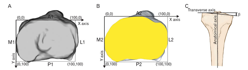
Fig. 1 (A) Schematic representation of the proximal tibia at the level of the tibial plateau shows how the four reference lines A1, P1, L1, and M1 were drawn. The coordinate system is also illustrated. (B) Schematic representation of a cross section of the tibia at a level 10 mm below the tibial plateau demonstrating how the four reference lines A2, P2, M2, and L2 were drawn. The coordinate system used at this level is also shown. (C) The diagram demonstrating how the β angle was estimated from the AP view of the tibia. The anatomical axis of the tibia and the transverse axis are also illustrated; the angle between the mediolateral plateau line (connecting the bottom of lateral plateau and medial plateau in anterior view) and the transverse axis is the β angle.
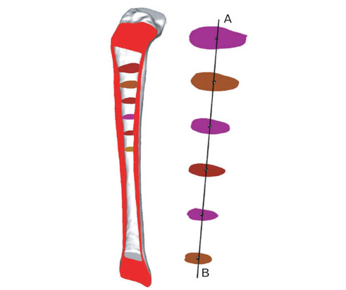
Fig. 2 Diagram showing the reconstruction of the tibial intramedullary canal axis. The six virtual cross sections used for calculations are shown. The centers of the cross sections are calculated as described in the text, and they are joined together resulting in the intramedullary canal axis represented by line AB.
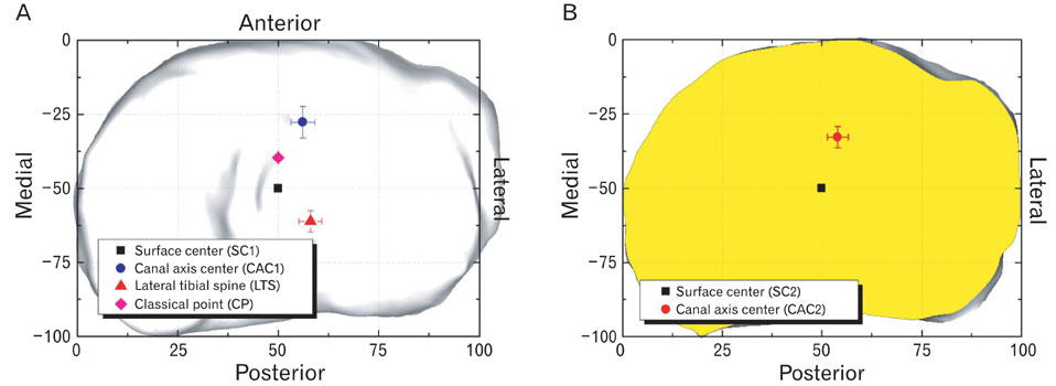
Fig. 3 (A) The diagram shows the coordinate system at the level of the tibial plateau with the LTS, SC1, CP, and combined CAC1 for males and females. Note the relationship between the proposed entry point CAC1, the classical entry point (CP) and the proposed landmark (LTS) to allow identification of the proper entry point. (B) The diagram shows the cross section of the tibia with the coordinate system at a level 10 mm below the tibial plateau with the surface center (the suggested intraoperative reference point) and the combined canal axis center for males and females demonstrating their relative positions. The canal axis center is the proposed entry point.
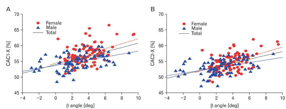
Fig. 4 (A) The β angle represents tibial varus bowing and is compared with lateral placement of the proposed entry point at the level of the tibial plateau (X coordinate of CAC1) in 200 tibiae in males and females. Lateral placement increases with increasing tibial varus bowing, more so for females than males. (B) The β angle represents tibial varus bowing and is compared with lateral placement of the proposed entry point at a level 10 mm below the tibial plateau (X coordinate of CAC2) in 200 tibiae in males and females. Here too Lateral placement increases with increasing tibial varus bowing, more so for females than males.
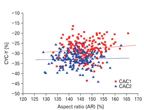
Fig. 5 The aspect ratio is compared with anteroposterior placement of the proposed entry point at the level of the tibial plateau (Y coordinate of CAC1) and at the level 10 mm below the tibial plateau (Y coordinate of CAC2).
Reference
-
1. Benjamin J. Component alignment in total knee arthroplasty. Instr Course Lect. 2006. 55:405–412.2. Bloebaum RD, Bachus KN, Mitchell W, Hoffman G, Hofmann AA. Analysis of the bone surface area in resected tibia. Implications in tibial component subsidence and fixation. Clin Orthop Relat Res. 1994. 309:2–10.3. Hicks CA, Noble P, Tullos H. The anatomy of the tibial intramedullary canal. Clin Orthop Relat Res. 1995. 321:111–116.4. Ishii Y, Ohmori G, Bechtold JE, Gustilo RB. Extramedullary versus intramedullary alignment guides in total knee arthroplasty. Clin Orthop Relat Res. 1995. 318:167–175.5. Matsui Y, Kadoya Y, Uehara K, Kobayashi A, Takaoka K. Rotational deformity in varus osteoarthritis of the knee: analysis with computed tomography. Clin Orthop Relat Res. 2005. 433:147–151.6. Moreland JR. Mechanisms of failure in total knee arthroplasty. Clin Orthop Relat Res. 1988. 226:49–64.7. Scuderi GR, Insall JN. The posterior stabilized knee prosthesis. Orthop Clin North Am. 1989. 20:71–78.8. Westrich GH, Haas SB, Insall JN, Frachie A. Resection specimen analysis of proximal tibial anatomy based on 100 total knee arthroplasty specimens. J Arthroplasty. 1995. 10:47–51.9. Whiteside LA, Summers RG. Anatomic landmarks for an intramedullary alignment system for total knee replacement. Orthop Trans. 1983. 7:546–547.
- Full Text Links
-
- Actions
-
Cited
- CITED
-
- Close
- Share
-
- Similar articles
-
- Three Dimensional Analysis for the Intramedullary Canal Axis of the Proximal Tibia: Clinical Relevance to Total Knee Arthroplasty
- Total Knee Arthroplasty using Intramedullary Tibial Cutting Guide
- Extramedullary Versus Intramedullary Alignment Guide Systems in Total Knee Arthroplasty
- A Bent Intramedullary Interlocking Tibial Nail: A Case Report
- Posterior Cortical Fracture of Tibia during Tibial Interlocking Intramedurally Nail Extraction : A report of 3 cases
