Prog Med Phys.
2015 Dec;26(4):215-222. 10.14316/pmp.2015.26.4.215.
Experimental Study for Phase-contrast X-ray Imaging Based on a Single Antiscatter Grid and a Polychromatic X-ray Source
- Affiliations
-
- 1Department of Radiation Convergence Engineering and i TOMO Research Group, Yonsei University, Wonju, Korea. hscho1@yonsei.ac.kr
- KMID: 2151754
- DOI: http://doi.org/10.14316/pmp.2015.26.4.215
Abstract
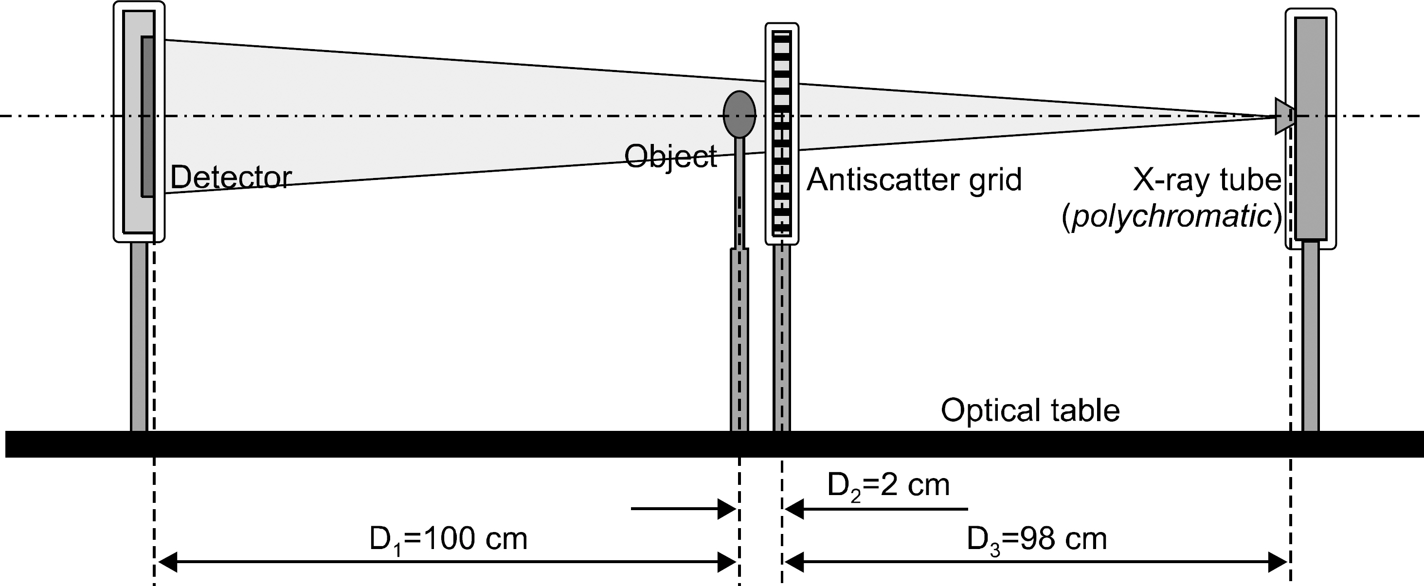
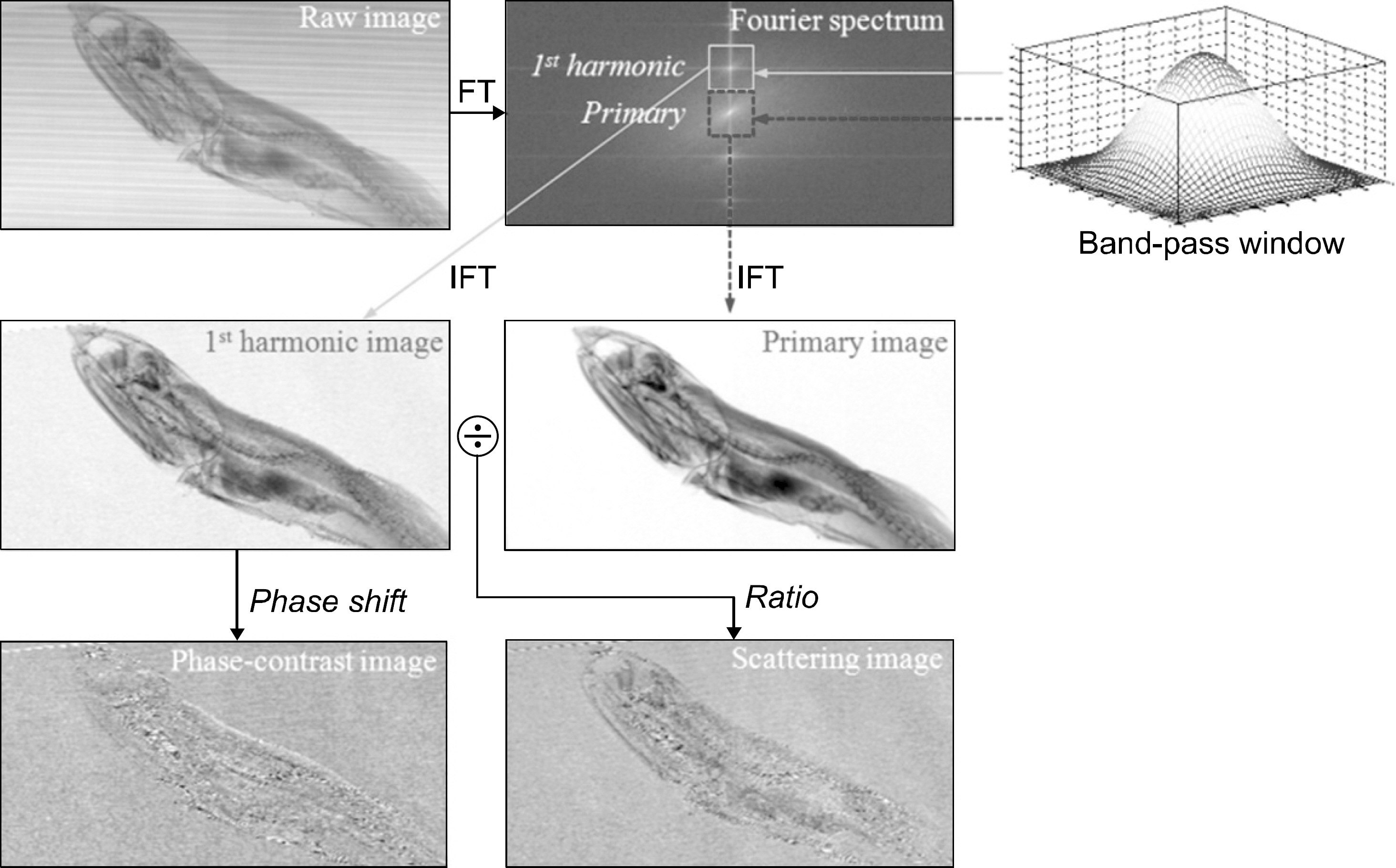
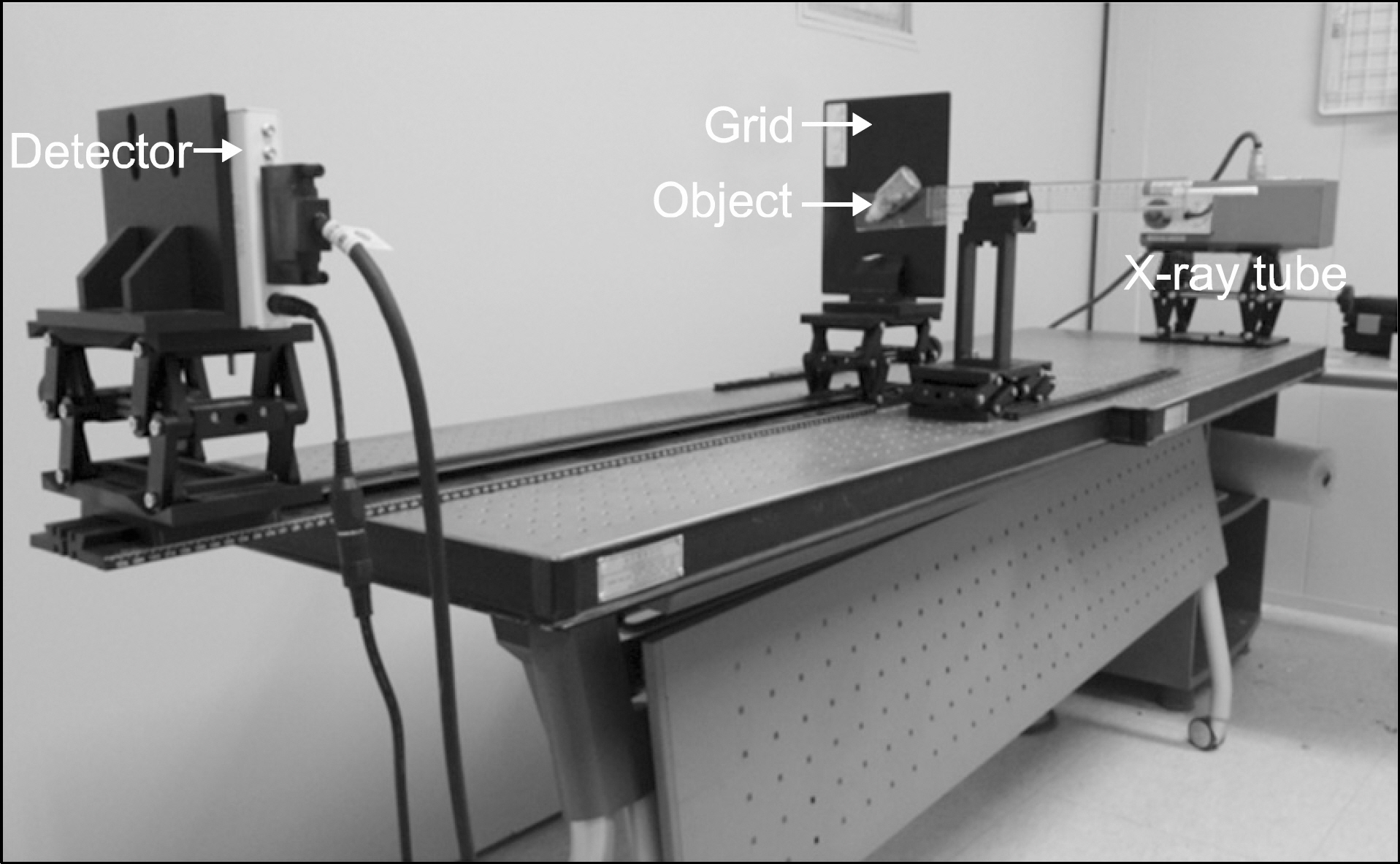
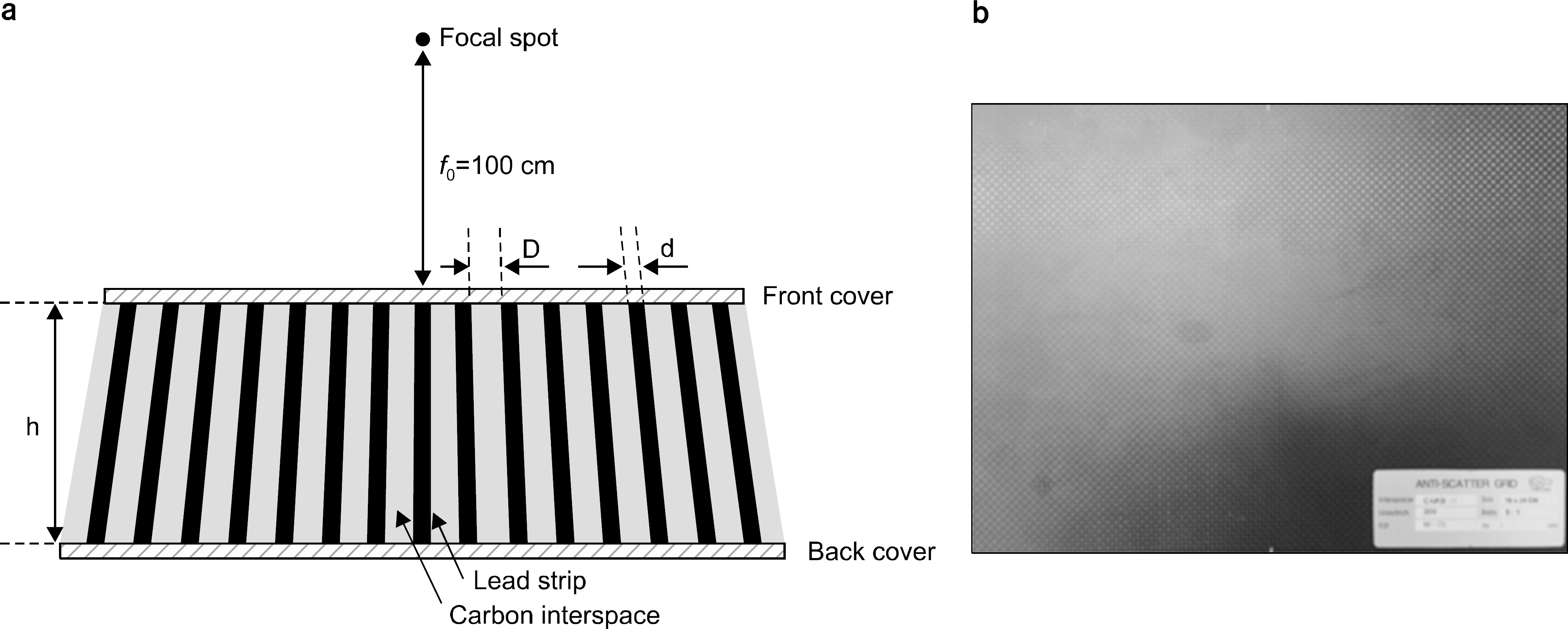
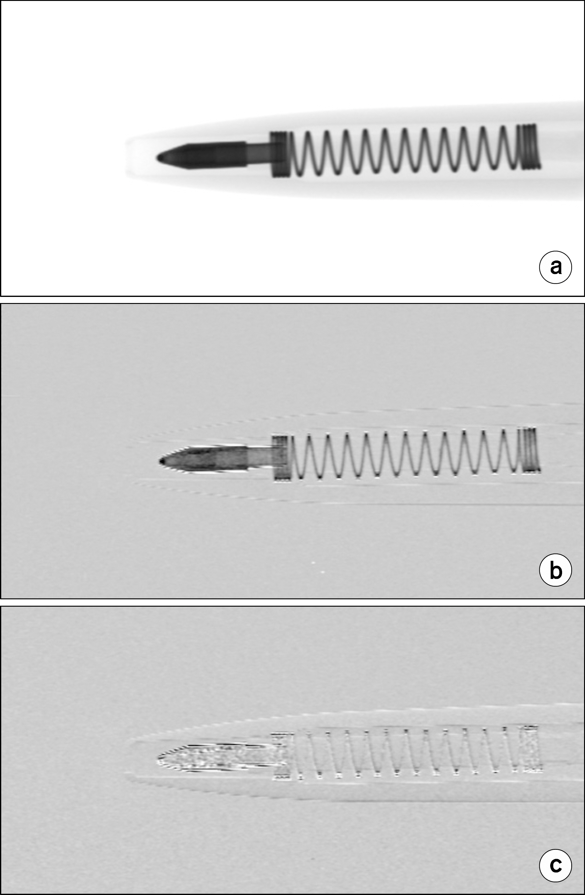
- In this work, we performed a proof-of-concept experiment for phase-contrast x-ray imaging (PCXI) based on a single antiscatter grid and a polychromatic x-ray source. We established a table-top setup which consists of a focused-linear grid having a strip density of 200 lines/inch, a microfocus x-ray tube having a focal-spot size of about 5 microm, and a CMOS-type flat-panel detector having a pixel size of 48 microm. By using our prototype PCXI system and the Fourier demodulation technique, we successfully obtained attenuation, scattering, and differential phase-contrast images of improved visibility from the raw images of several selected samples at x-ray tube conditions of 90 kVp and 0.1 mAs. Further, fusion image (e.g., the attenuation+the scattering) may have an advantage in displaying details of the sample's structures that are not clearly visible in the conventional attenuation image. Our experimental results indicate that single-grid-based approach seems a useful method for PCXI with great simplicity and minimal requirements on the setup alignment.
Figure
Reference
-
References
1. D. Chapman, W. Thomlinson, R. Johnston, et al: Diffraction enhanced x-ray imaging. Phys. Med. Biol. 42(11):2015–2025. 1997.2. L. Levine and G. Long: X-ray imaging with ultra-small-angle x-ray scattering as a contrast mechanism. J. Appl. Crystallogr. 37:757–765. 2004.3. H. Wen, E. Bennett, R. Kopace, A. Stein, and V. Pai: Single-shot x-ray differential phase-contrast and diffraction imaging using two-dimensional transmission gratings. Opt. Lett. 35(12):1932–1934. 2010.4. M. Endrizzi, P. Diemoz, T. Millard, et al: Hard X-ray dark-field imaging with incoherent sample illumination. Appl. Phys. Lett. 104:024106. 2014.5. T. Davis, D. Gao, T. Gureyev, A. Stevenson, and S. Wilkins: Phase-contrast imaging of weakly absorbing materials using hard x-rays. Nature. 373:595–598. 1995.6. M. Ando, K. Yamasaki, F. Toyofuku, et al: Attempt at visu alizing breast cancer with x-ray dark field imaging. Japan J. Appl. Phys. 44(17):L528–L531. 2005.7. H. Wen, E. Bennett, M. Hegedus, and S. Rapacchi: Fourier x-ray scattering radiography yields bone structural information. Radiology. 251(3):910–918. 2009.8. H. Wen, E. Bennett, M. Hegedus, and S. Carroll: Spatial harmonic imaging of x-ray scattering-Initial results. IEEE Trans. Med. Imaging. 27(8):997–1002. 2008.9. C. Kottler, C. David, F. Pfeiffer, and O. Bunk: A two-directional approach for grating based differential phase contrast imaging using hard x-rays. Opt. Express. 15:1175–1181. 2007.
- Full Text Links
- Actions
-
Cited
- CITED
-
- Close
- Share
- Similar articles
-
- Numerical Modeling and Experiment for Single Grid-Based Phase-Contrast X-Ray Imaging
- Effect of a prototype 2-dimensional antiscatter grid on image quality obtained with a dental cone-beam computed tomography scanner
- Phase Contrast Microradiography of Mouse Lung Using Synchrotron X-ray: Correlation with Optical Microscopy
- Synchrotron Radiation Imaging of Breast Tissue Using a Phase-contrast Hard X-ray Microscope
- Synchrotron Radiation Imaging of Female Breast Tissues Using Phase Contrast Technique

