Plain Radiography of the Hip: A Review of Radiographic Techniques and Image Features
- Affiliations
-
- 1Department of Orthopaedic Surgery, Samsung Medical Center, Sungkyunkwan University School of Medicine, Seoul, Korea. limsj@skku.edu
- KMID: 2069141
- DOI: http://doi.org/10.5371/hp.2015.27.3.125
Abstract
- Plain radiographic examination is a fundamental approach to the diagnosis and treatment decision-making of the hip. A thorough understanding of standard radiographic techniques, radiographic anatomy, and disease patterns affecting the hip can be helpful in improving diagnostic accuracy. This article reviews the standard protocols used to obtain radiographic projections of the hip and addresses specific signs and various radiographic measurements used to adequately and reliably recognize structural diseases of the hip.
Keyword
MeSH Terms
Figure
-
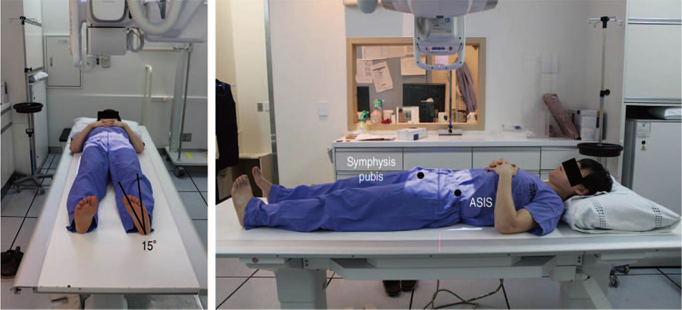
Fig. 1 Positioning for an anteroposterior hip radiograph. In a supine position, the image is taken toward the middle of the line connecting the upper part of the symphysis pubis and anterior-superior iliac spine (ASIS); either both patellae should be facing forward or lower extremities should be internally rotated by 15°-20° to accommodate femoral anteversion in anteroposterior hip radiographs.
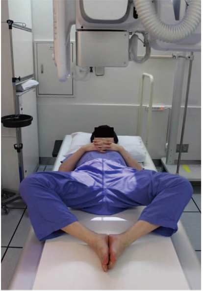
Fig. 2 Positioning for a frog-leg lateral view. The knee joint is flexed 30°-40° in a supine position while the hip is externally rotated by 45° so that the image is taken toward the middle of a line connecting the upper symphysis pubica and anterior-superior iliac spine.

Fig. 3 Positioning for a Löwenstein view. Patient is turned onto the affected hip at least 45° with the hip flexion angle of 90° and an internal rotation angle of 45° in a supine position and then images of each side are taken vertically from the groin region.
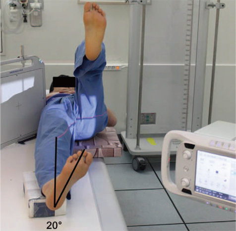
Fig. 4 Positioning for the cross-table lateral view. A lower extremity is internally rotated by 15°-20° in a supine position and then the hip and knee joints on the other side are flexed to prevent interference in radiographic projection; a cassette is positioned on the side of the hip at the right angle relative to the incidence angle, thereby projecting toward the groin region at 35°-45° of incidence parallel to the longitudinal axis of the femur.

Fig. 5 Positioning for false-profile view. The pelvis is rotated 65° relative to the bucky wall stand, with the foot on the affected side parallel to the radiographic cassette.

Fig. 6 Standard anteroposterior hip radiograph. The coccyx and symphysis pubis are in a straight line and are positioned in the middle line of the image; both sides of the iliac wings and obturator foramina are symmetric, while the distance between the superior border of the pubic symphysis and the tip of the coccyx is between 1 and 3 cm.
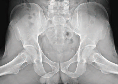
Fig. 7 Frog-leg lateral view.
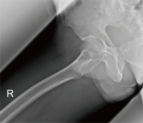
Fig. 8 Löwenstein view.

Fig. 9 Cross-table lateral view.

Fig. 10 False-profile view.

Fig. 11 Leg length. Leg length difference is assessed by measuring the difference in distance between the most prominent part of the lesser trochanter and a parallel line connecting the teardrops.

Fig. 12 Neck-shaft angles. (A) Normal, (B) coxa valga, (C) coxa vara.

Fig. 13 Acetabular coverages. (A) Lateral center-edge (CE) angle 34°, femoral head extrusion index 17% (normal acetabulum); (B) lateral CE angle 12°, femoral head extrusion index 48% (acetabular dysplasia).
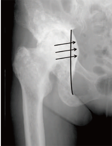
Fig. 14 Acetabular depth. The radiographic appearance of protrusio acetabuli, with the acetabular fossa and femoral head being displaced medial to the ilioischial line.

Fig. 15 Acetabular inclinations. (A) Tönnis angle 5° (normal), (B) Tönnis angle 30°(increased likelihood of hip instability).

Fig. 16 Acetabular versions. (A) Anteversion. (B) Retroversion; a crossover sign or figure-of-eight sign, a posterior wall deficiency sign, and an ischial spine sign (arrowhead). AW: anterior wall, PW: posterior wall.
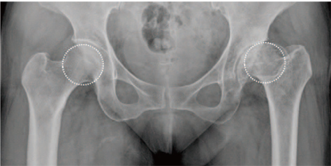
Fig. 17 Head sphericity. Nonspherical femoral head (left) and spherical femoral head (right) confirmed using the reference circle.

Fig. 18 Joint space width. Normal joint space (left) and joint space narrowed due to arthritis (right).
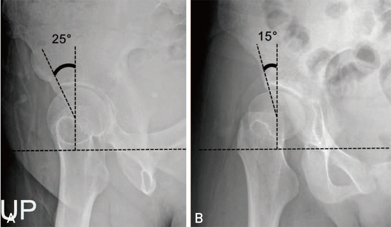
Fig. 19 Anterior center-edge angles on a false-profile view. (A) 25°(normal), (B) 15°(lack of anterior coverage).

Fig. 20 Femoral head-neck offset ratio. This ratio can be assessed using three lines: (1) a horizontal line between the center of the long axis of the femoral neck and the center of the femoral head; (2) a line parallel to line 1 through the anteriormost aspect of the femoral neck; and (3) a line parallel to line 1 through the anteriormost aspect of the femoral head. The head-neck offset ratio is calculated by dividing the distance between lines 2 and 3 by the diameter of the femoral head. The figure depicts a normal case where the head-neck offset ratio is 0.26.
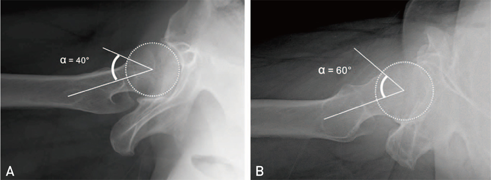
Fig. 21 Alpha angles. This angle can be assessed by measuring the angle between a line connecting the center of the long axis of the femoral neck and the center of the femoral head, and a line from the center of the femoral head to the point on the anterolateral head-neck junction where the radius of the femoral head begins to increase beyond the radius found more centrally in the acetabulum, where the head is more spherical. If the alpha angle exceeds 50°-55°, a cam deformity is diagnosed. (A) The alpha angle is 40° (normal). (B) The alpha angle is 60° (abnormal: cam deformity).
Reference
-
1. Callaghan JJ, Rosenberg AG, Rubash HE. The adult hip. 2nd ed. Philadelphia: Lippincott Williams & Wilkins;2007. p. 349–391.2. Tannast M, Zheng G, Anderegg C, et al. Tilt and rotation correction of acetabular version on pelvic radiographs. Clin Orthop Relat Res. 2005; 438:182–190.
Article3. Hananouchi T, Sugano N, Nakamura N, et al. Preoperative templating of femoral components on plain X-rays Rotational evaluation with synthetic X-rays on ORTHODOC. Arch Orthop Trauma Surg. 2007; 127:381–385.
Article4. Clohisy JC, Carlisle JC, Beaulé PE, et al. A systematic approach to the plain radiographic evaluation of the young adult hip. J Bone Joint Surg Am. 2008; 90:Suppl 4. 47–66.
Article5. Engesæter IØ, Laborie LB, Lehmann TG, et al. Radiological findings for hip dysplasia at skeletal maturity. Validation of digital and manual measurement techniques. Skeletal Radiol. 2012; 41:775–785.
Article6. Jamali AA, Mladenov K, Meyer DC, et al. Anteroposterior pelvic radiographs to assess acetabular retroversion: high validity of the "cross-over-sign". J Orthop Res. 2007; 25:758–765.
Article7. Kalberer F, Sierra RJ, Madan SS, Ganz R, Leunig M. Ischial spine projection into the pelvis: a new sign for acetabular retroversion. Clin Orthop Relat Res. 2008; 466:677–683.8. Chosa E, Tajima N. Anterior acetabular head index of the hip on false-profile views New index of anterior acetabular cover. J Bone Joint Surg Br. 2003; 85:826–829.9. Tannast M, Siebenrock KA, Anderson SE. Femoroacetabular impingement: radiographic diagnosis--what the radiologist should know. AJR Am J Roentgenol. 2007; 188:1540–1552.
Article10. Eijer H, Leunig M, Mahomed M, Ganz R. Cross-table lateral radiograph for screening of anterior femoral head-neck offset in patients with femoroacetabular impingement. Hip Int. 2001; 11:37–41.
Article
- Full Text Links
-
- Actions
-
Cited
- CITED
-
- Close
- Share
-
- Similar articles
-
- Hip and Pelvis Diseases on Lumbar AP Radiographs Including Both Hip Joints
- Plain Abdominal Radiography in Infants and Children
- Comparative study of radiography and scintigraphy for loosening and infection of prosthetic hip replacement
- Changes of the hip joints associated with chronic subluxation and dislocation: CT and plain radiographic analysis
- Common positioning errors in panoramic radiography: A review
