A method for mandibular dental arch superimposition using 3D cone beam CT and orthodontic 3D digital model
- Affiliations
-
- 1Department of Orthodontics, Graduate School, Kyung Hee University School of Dentistry, Seoul, Korea. kislee@khu.ac.kr
- KMID: 1435411
- DOI: http://doi.org/10.4041/kjod.2012.42.4.169
Abstract
OBJECTIVE
The purpose of this study was to develop superimposition method on the lower arch using 3-dimensional (3D) cone beam computed tomography (CBCT) images and orthodontic 3D digital modeling.
METHODS
Integrated 3D CBCT images were acquired by substituting the dental portion of 3D CBCT images with precise dental images of an orthodontic 3D digital model. Images were acquired before and after treatment. For the superimposition, 2 superimposition methods were designed. Surface superimposition was based on the basal bone structure of the mandible by surface-to-surface matching (best-fit method). Plane superimposition was based on anatomical structures (mental and lingual foramen). For the evaluation, 10 landmarks including teeth and anatomic structures were assigned, and 30 times of superimpositions and measurements were performed to determine the more reproducible and reliable method.
RESULTS
All landmarks demonstrated that the surface superimposition method produced relatively more consistent coordinate values. The mean distances of measured landmarks values from the means were statistically significantly lower with the surface superimpositions method.
CONCLUSIONS
Between the 2 superimposition methods designed for the evaluation of 3D changes in the lower arch, surface superimposition was the simpler, more reproducible, reliable method.
Figure
-
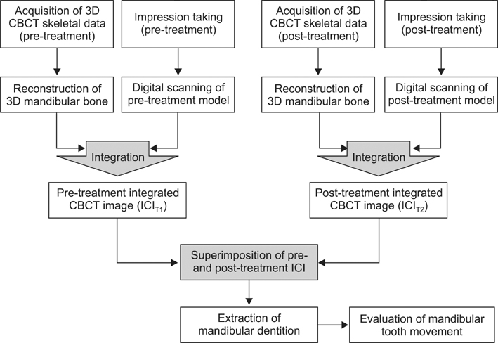
Figure 1 Overall procedure of the mandibular dental arch superimposition method. 3D, 3-dimensional; CBCT, cone beam computed tomography; ICI, integrated 3D CBCT image; T1, pre-treatment; T2, post-treatment.
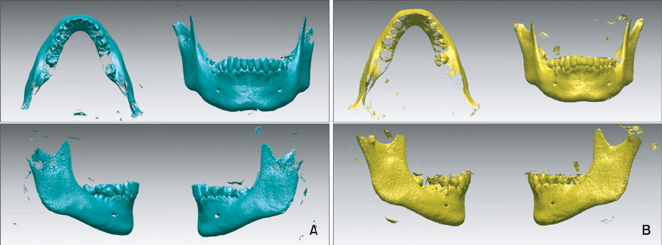
Figure 2 Reconstructed 3-dimensional image of the mandible. A, Pre-treatment; B, post-treatment.
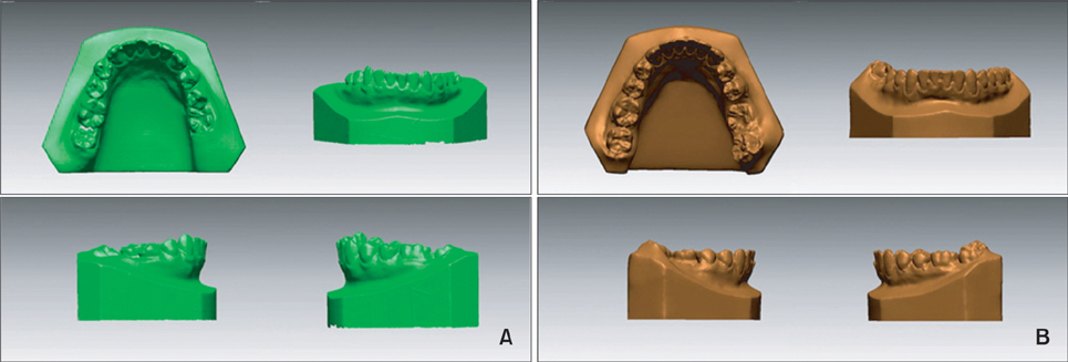
Figure 3 Orthodontic 3-dimensional digital model of mandibular dentition. A, Pre-treatment; B, post-treatment.
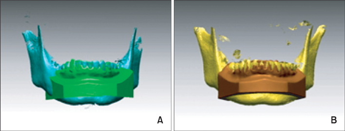
Figure 4 Preliminary fusion model by surface-to-surface matching (best-fit method). A, Pre-treatment; B, post-treatment.
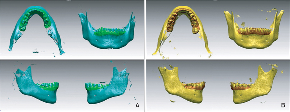
Figure 5 Final individual integrated 3D CBCT image of the mandible. A, Pre-treatment; B, post-treatment. 3D, 3-dimensional; CBCT, cone beam computed tomography.
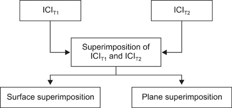
Figure 6 Two different registration methods designed for superimposing ICIT1 and ICIT2. ICI, Integrated 3D CBCT image; T1, pre-treatment; T2, post-treatment.
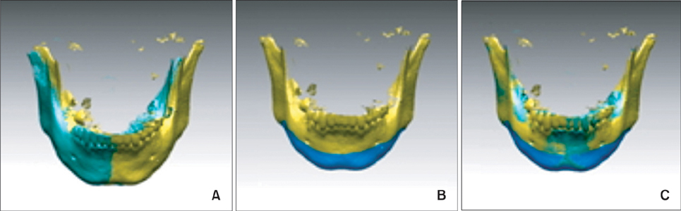
Figure 7 The procedure for surface superimposition. A, Selecting 2 ICI. B, Selecting the registration area (the inferior portion of mandible body and posterior portion of mandible ramus were selected). C, Superimposed ICIT1 and ICIT2 by surface-to-surface matching (best-fit method). ICI, Integrated 3D CBCT image.
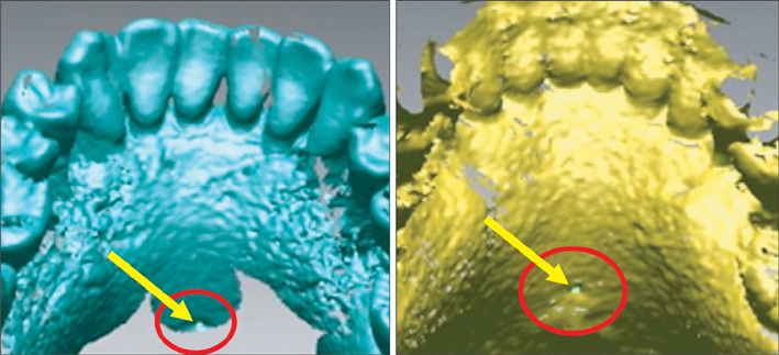
Figure 8 Aspect for the examination of lingual foramen. Arrows indicate the orifice of the lingual foramen.
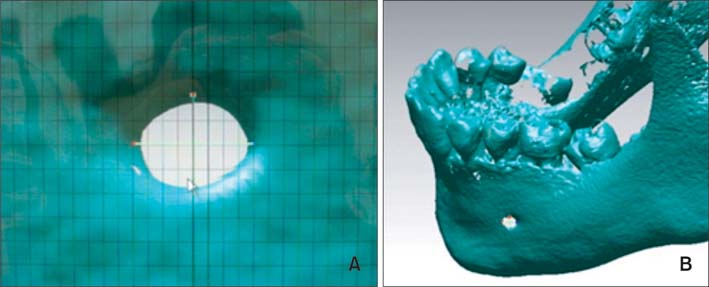
Figure 9 The center of the foramen was selected with a grid on the monitor by selecting 4 points of the foramen, the most superior, inferior and both lateral points, with the mandible rotated to give a perpendicular view to the foramen. Each procedure was performed on each mental foramen and lingual foramen on both ICIT1 and ICIT2. ICI, Integrated 3D CBCT image; T1, pre-treatment; T2, post-treatment.
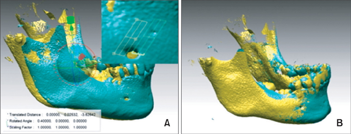
Figure 10 The procedure for plane superimposition. A, Selecting 2 ICI with the constituted plane. B, Superimposed ICIT1 and ICIT2 with the registration of 2 anatomical structure oriented planes. ICI, Integrated 3D CBCT image; T1, pre-treatment; T2, post-treatment.
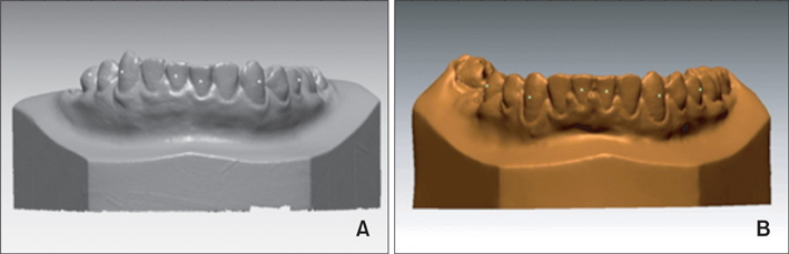
Figure 11 Facial axis points are marked on the lower central incisor, canine, and 2nd premolar on both left and right sides. White-spots indicate the marked points. A, Pre-treatment model; B, post-treatment model.
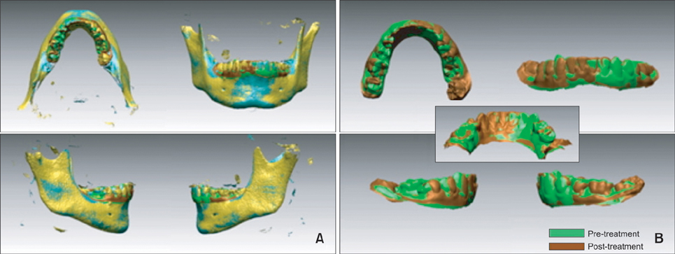
Figure 12 The dentition extracted from the superimposed image. A, Combined image, B, dentition was extracted.
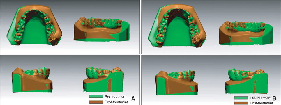
Figure 13 Final image of superimposed mandibular dental arch. A, By surface superimposition; B, by plane superimposition.
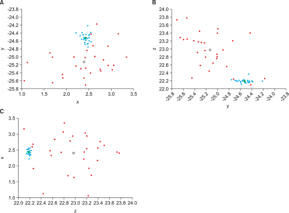
Figure 14 Scatter plot of post-treatment coordinate values of the lower left incisor after 2 superimposition methods. Blue dot, point from surface superimposition; red cross, point from plane superimposition; green dot, mean coordinate value of lower left incisor after 30 trials of surface superimposition; black circle, mean coordinate value of lower left incisor after 30 trials of plane superimposition. A, x-y axis; B, y-z axis; C, z-x axis. The scatter plot shows the reproducibility with the surface superimposition method and the large variation of points generated by the plane superimposition method.
Cited by 2 articles
-
Comparison of cone-beam computed tomography cephalometric measurements using a midsagittal projection and conventional two-dimensional cephalometric measurements
Pil-Kyo Jung, Gung-Chol Lee, Cheol-Hyun Moon
Korean J Orthod. 2015;45(6):282-288. doi: 10.4041/kjod.2015.45.6.282.In-vitro assessment of the accuracy and reliability of mandibular dental model superimposition based on voxel-based cone-beam computed tomography registration
Gaofeng Han, Jing Li, Shuo Wang, Yan Liu, Xuedong Wang, Yanheng Zhou
Korean J Orthod. 2019;49(2):97-105. doi: 10.4041/kjod.2019.49.2.97.
Reference
-
1. van der Linden FP. Changes in the position of posterior teeth in relation to ruga points. Am J Orthod. 1978. 74:142–161.
Article2. Lebret L. Growth changes of the palate. J Dent Res. 1962. 41:1391–1404.
Article3. Peavy DC Jr, Kendrick GS. The effects of tooth movement on the palatine rugae. J Prosthet Dent. 1967. 18:536–542.
Article4. English WR, Robison SF, Summitt JB, Oesterle LJ, Brannon RB, Morlang WM. Individuality of human palatal rugae. J Forensic Sci. 1988. 33:718–726.
Article5. Almeida MA, Phillips C, Kula K, Tulloch C. Stability of the palatal rugae as landmarks for analysis of dental casts. Angle Orthod. 1995. 65:43–48.6. Bailey LT, Esmailnejad A, Almeida MA. Stability of the palatal rugae as landmarks for analysis of dental casts in extraction and nonextraction cases. Angle Orthod. 1996. 66:73–78.7. Hoggan BR, Sadowsky C. The use of palatal rugae for the assessment of anteroposterior tooth movements. Am J Orthod Dentofacial Orthop. 2001. 119:482–488.
Article8. Ashmore JL, Kurland BF, King GJ, Wheeler TT, Ghafari J, Ramsay DS. A 3-dimensional analysis of molar movement during headgear treatment. Am J Orthod Dentofacial Orthop. 2002. 121:18–29.
Article9. Miller RJ, Kuo E, Choi W. Validation of Align Technology's Treat III digital model superimposition tool and its case application. Orthod Craniofac Res. 2003. 6:Suppl 1. 143–149.
Article10. Ghafari J, Baumrind S, Efstratiadis SS. Misinterpreting growth and treatment outcome from serial cephalographs. Clin Orthod Res. 1998. 1:102–106.
Article11. Cha BK, Lee JY, Jost-Brinkmann PG, Yoshida N. Analysis of tooth movement in extraction cases using three-dimensional reverse engineering technology. Eur J Orthod. 2007. 29:325–331.
Article12. Commer P, Bourauel C, Maier K, Jäger A. Construction and testing of a computer-based intraoral laser scanner for determining tooth positions. Med Eng Phys. 2000. 22:625–635.
Article13. McDonagh S, Moss JP, Goodwin P, Lee RT. A prospective optical surface scanning and cephalometric assessment of the effect of functional appliances on the soft tissues. Eur J Orthod. 2001. 23:115–126.
Article14. Goaz PW, White SC. Oral radiology; Principles and interpretation. 1987. 2nd ed. Toronto: Mosby;189–190.15. Kasle MJ. An atlas of dental radiographic anatomy. 1989. 3rd ed. Toronto: Saunders.16. Andrews LF. Straight wire: The concept and appliance. 1989. San Diego: L.A. Wells.17. Girod S, Keeve E, Girod B. Advances in interactive craniofacial surgery planning by 3D simulation and visualization. Int J Oral Maxillofac Surg. 1995. 24:120–125.
Article18. Chen LH, Chen WH. Three-dimensional computer-assisted simulation combining facial skeleton with facial morphology for orthognathic surgery. Int J Adult Orthodon Orthognath Surg. 1999. 14:140–145.19. Motohashi N, Kuroda T. A 3D computer-aided design system applied to diagnosis and treatment planning in orthodontics and orthognathic surgery. Eur J Orthod. 1999. 21:263–274.
Article20. Xia J, Samman N, Yeung RW, Shen SG, Wang D, Ip HH, et al. Three-dimensional virtual reality surgical planning and simulation workbench for orthognathic surgery. Int J Adult Orthodon Orthognath Surg. 2000. 15:265–282.21. Ferrario VF, Sforza C, Poggio CE, Serrao G. Facial three-dimensional morphometry. Am J Orthod Dentofacial Orthop. 1996. 109:86–93.
Article22. Gateno J, Xia J, Teichgraeber JF, Rosen A. A new technique for the creation of a computerized composite skull model. J Oral Maxillofac Surg. 2003. 61:222–227.
Article23. Svendsen P, Quiding L, Landahl I. Blackout and other artefacts in computed tomography caused by fillings in teeth. Neuroradiology. 1980. 19:229–234.
Article24. Swennen GR, Barth EL, Eulzer C, Schutyser F. The use of a new 3D splint and double CT scan procedure to obtain an accurate anatomic virtual augmented model of the skull. Int J Oral Maxillofac Surg. 2007. 36:146–152.
Article25. Nkenke E, Zachow S, Benz M, Maier T, Veit K, Kramer M, et al. Fusion of computed tomography data and optical 3D images of the dentition for streak artefact correction in the simulation of orthognathic surgery. Dentomaxillofac Radiol. 2004. 33:226–232.
Article26. Nishii Y, Nojima K, Takane Y, Isshiki Y. Integration of the maxillofacial three-dimensional CT image and the three-dimensional dental surface image. Orthod Waves. 1998. 57:189–194.27. Subsol G, Thirion JP, Ayache N. A scheme for automatically building three-dimensional morphometric anatomical atlases: application to a skull atlas. Med Image Anal. 1998. 2:37–60.
Article28. McDonnell D, Reza Nouri M, Todd ME. The mandibular lingual foramen: a consistent arterial foramen in the middle of the mandible. J Anat. 1994. 184:363–369.29. Cevidanes LH, Bailey LJ, Tucker GR Jr, Styner MA, Mol A, Phillips CL, et al. Superimposition of 3D cone-beam CT models of orthognathic surgery patients. Dentomaxillofac Radiol. 2005. 34:369–375.
Article30. Kawamata A, Fujishita M, Nagahara K, Kanematu N, Niwa K, Langlais RP. Three-dimensional computed tomography evaluation of postsurgical condylar displacement after mandibular osteotomy. Oral Surg Oral Med Oral Pathol Oral Radiol Endod. 1998. 85:371–376.
Article
- Full Text Links
-
- Actions
-
Cited
- CITED
-
- Close
- Share
-
- Similar articles
-
- In-vitro assessment of the accuracy and reliability of mandibular dental model superimposition based on voxel-based cone-beam computed tomography registration
- Comparison of digital models generated from three-dimensional optical scanner and cone beam computed tomography
- Accuracy of Bolton analysis measured in laser scanned digital models compared with plaster models (gold standard) and cone-beam computer tomography images
- Validity of Three-dimensional Facial Scan Taken with Facial Scanner and Digital Photo Wrapping on the Cone-beam Computed Tomography: Comparison of Soft Tissue Parameters
- Three-dimensional structural analysis of the morphological condition of the alveolar bone before and after orthodontic treatment
