Korean J Orthod.
2009 Oct;39(5):289-299.
Use of Head Posture Aligner to improve accuracy of frontal cephalograms generated from cone-beam CT scans
- Affiliations
-
- 1Department of Orthodontics, 2nd Stage of Brain Korea 21, Dental Science Research Institute, School of Dentistry, Chonnam National University, Korea. hhwang@chonnam.ac.kr
Abstract
OBJECTIVE
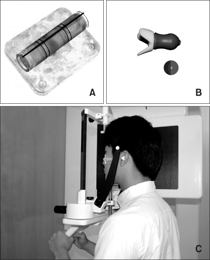
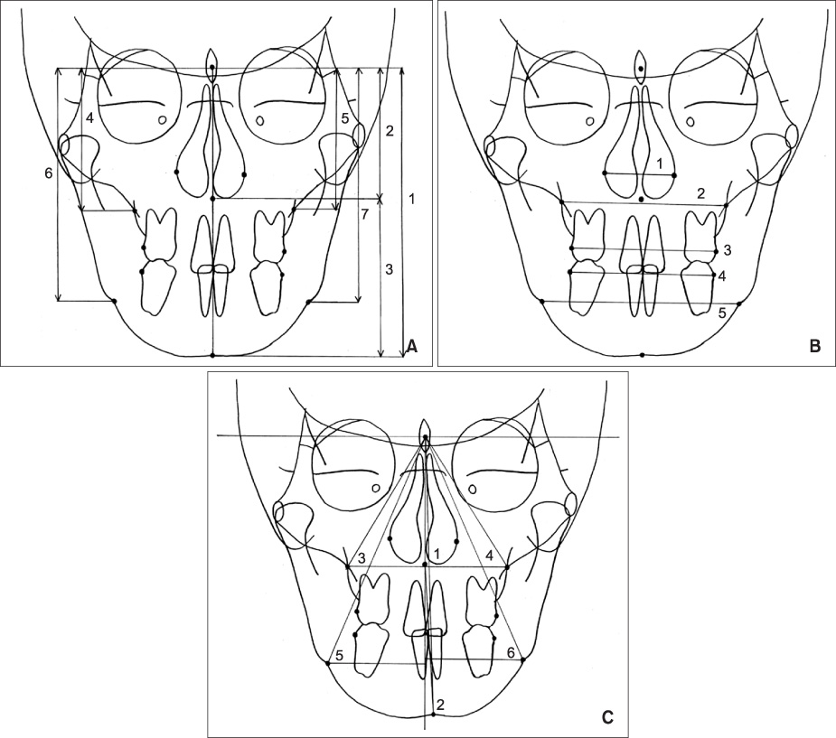
The purpose of the present study was to evaluate the effectiveness of the use of Head Posture Aligner (HPA) during cone-beam computed tomography (CBCT) scan in generation of frontal cephalograms using 3D CBCT images.
METHODS
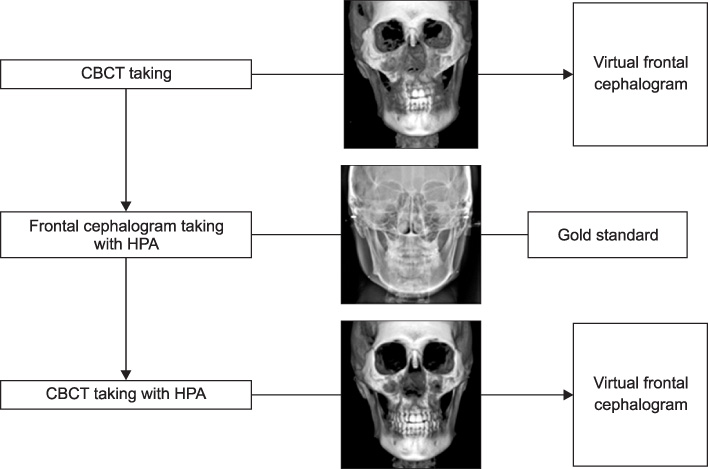
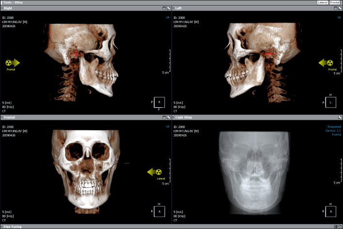
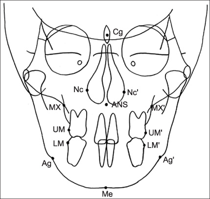
CBCT scans and frontal cephalograms were made in 30 adult individuals. While a couple of CBCT scan was made for one subject, one was made with conventional method, without use of HPA, the other was acquired with the use of HPA. After creation of virtual frontal cephalogram from each 3D CBCT image, it was traced and compared with the tracing of real frontal cephalogram.
RESULTS
In the comparison of the measurements, the virtual cephalograms with the use of HPA did not show statistically significant differences with the real cephalograms whereas the virtual cephalograms without the use of HPA presented significant differences with real cephalograms in many measurements. In the correlation analysis with the measurements of the real cephalograms, the virtual cephalograms with the use of HPA showed higher correlations in all measurements than the virtual cephalograms without the use of HPA.
CONCLUSIONS
Measurements from CBCT-generated cephalograms become similar to those from real cephalograms with the use of HPA during CBCT scan. Thus, the use of HPA is suggested during the CBCT scan in order to construct accurate virtual frontal cephalograms using 3D CBCT images.
Figure
Reference
-
1. Vannier MW, Marsh JL, Warren JO. Three dimensional CT reconstruction images for craniofacial surgical planning and evaluation. Radiology. 1984. 150:179–184.
Article2. Mozzo P, Procacci C, Tacconi A, Martini PT, Andreis IA. A new volumetric CT machine for dental imaging based on the cone-beam technique: preliminary results. Eur Radiol. 1998. 8:1558–1564.
Article3. Mah JK, Danforth RA, Bumann A, Hatcher D. Radiation absorbed in maxillofacial imaging with a new dental computed tomography device. Oral Surg Oral Med Oral Pathol Oral Radiol Endod. 2003. 96:508–513.
Article4. Tsiklakis K, Donta C, Gavala S, Karayianni K, Kamenopoulou V, Hourdakis CJ. Dose reduction in maxillofacial imaging using low dose cone beam CT. Eur J Radiol. 2005. 56:413–417.
Article5. Swennen GR, Schutyser F. Three-dimensional cephalometry: spiral multi-slice vs cone-beam computed tomography. Am J Orthod Dentofacial Orhtop. 2006. 130:410–416.
Article6. Hechler SL. Cone-beam CT: applications in orthodontics. Dent Clin North Am. 2008. 52:809–823.
Article7. Farman AG. ALARA still applies. Oral Surg Oral Med Oral Pathol Oral Radiol Endod. 2005. 100:395–397.
Article8. Mah J, Hatcher D. Current status and future needs in craniofacial imaging. Orthod Craniofac Res. 2003. 6:179–182.
Article9. Farman AG, Scarfe WC. Development of imaging selection criteria and procedures should precede cephalometric assessment with cone-beam computed tomography. Am J Orthod Dentofacial Orthop. 2006. 130:257–265.
Article10. Moshiri M, Scarfe WC, Hilgers ML, Scheetz JP, Silveira AM, Farman AG. Accuracy of linear measurements from imaging plate and lateral cephalometric images derived from cone-beam computed tomography. Am J Orthod Dentofacial Orthop. 2007. 132:550–560.
Article11. Kumar V, Ludlow JB, Mol A, Cevidanes LH. Comparison of conventional and cone beam CT synthesized cephalograms. Dentomaxillofac Radiol. 2007. 36:263–269.
Article12. van Vlijmen OJ, Bergé SJ, Swennen GR, Bronkhorst EM, Katsaros C, Kuijpers-Jagtman AM. Comparison of cephalometric radiographs obtained from cone-beam computed tomography scans and conventional radiographs. J Oral Maxillofac Surg. 2009. 67:92–97.
Article13. Kang JY, Lim SH, Kim KW. The reliability of the cephalogram generated from cone-beam CT. Korean J Orthod. 2007. 37:391–399.14. Kumar V, Ludlow J, Soares Cevidanes LH, Mol A. In vivo comparison of conventional and cone beam CT synthesized cephalograms. Angle Orthod. 2008. 78:873–879.
Article15. Cattaneo PM, Bloch CB, Calmar D, Hjortshøj M, Melsen B. Comparison between conventional and cone-beam computed tomography-generated cephalograms. Am J Orthod Dentofacial Orthop. 2008. 134:798–802.
Article16. van Vlijmen OJ, Bergé SJ, Bronkhorst EM, Swennen GR, Katsaros C, Kuijpers-Jagtman AM. A comparison of frontal radiographs obtained from cone beam CT scans and conventional frontal radiographs of human skulls. Int J Oral Maxillofac Surg. 2009. 38:773–778.
Article17. Kim EH, Hwang HS. The validity of Head Posture Aligner in posteroanterior cephalometry. Korean J Orthod. 2000. 30:543–552.18. HS Hwang . Ear plug for forming reference axis in CT taking. Korean Patent. 10-0884354. 2009.19. Dahlberg G. Statistical methods for medical and biological students. 1940. London: George Allen & Unwin Ltd.;122–132.20. Scarfe WC, Farman AG, Sukovic P. Clinical applications of cone-beam computed tomography in dental practice. J Can Dent Assoc. 2006. 72:75–80.21. Cattaneo PM, Melsen B. The use of cone-beam computed tomography in an orthodontic department in between research and daily clinic. World J Orthod. 2008. 9:269–282.22. Showfety KJ, Vig PS, Matteson S. A simple method for taking natural-head-position cephalograms. Am J Orthod. 1983. 83:495–500.
Article
- Full Text Links
- Actions
-
Cited
- CITED
-
- Close
- Share
- Similar articles
-
- Accuracy of virtual 3-dimensional cephalometric images constructed with 2-dimensional cephalograms using the biplanar radiography principle
- Use of Reference Ear Plug to improve accuracy of lateral cephalograms generated from cone-beam computed tomography scans
- A comparative study of the reproducibility of landmark identification on posteroanterior and anteroposterior cephalograms generated from cone-beam computed tomography scans
- Three-dimensional CT image study on the correction of gonial angle width enlarged on frontal cephalogram
- The reliability of the cephalogram generated from cone-beam CT

