Modulation Transfer Function with Aluminum Sheets of Varying Thickness
- Affiliations
-
- 1Research Center, Dongnam Institute of Radiological and Medical Sciences, Busan, Korea. physics7@empas.com
- 2Department of Radiation Oncology, Dongnam Institute of Radiological and Medical Sciences, Busan, Korea.
- KMID: 2328189
- DOI: http://doi.org/10.14316/pmp.2016.27.2.55
Abstract
- We studied the method to gain a clear LSF using a thick aluminum sheet and to acquire the spatial resolution value with a high accuracy for a low spatial resolution imaging modality. In this study, aluminum sheets with thicknesses varying from 0.3 mm to 1.2 mm were tested to derive a modulation transfer function (MTF) for the oversampling and non-oversampling methods. The results were evaluated to verify the feasibility of the use of thick sheets for periodic quality assurance. Oversampling was more accurate than non-oversampling, and an aluminum sheet with a correction factor less than 2 at the cut-off frequency, which was less than 0.8 mm in this case, was confirmed to be suitable for MTF measurements. Therefore, MTF derivation from a thick aluminum sheet with thickness correction is plausible for a medical imaging modality.
MeSH Terms
Figure
-

Fig. 1. Aluminum sheet images in the transverse plane for parallel non-oversampling LSF (left) and tilted oversampling LSF (right). The LSF was determined by the sum of all the vertical projections across the plane within the regions of interest (red boxes). Phase correction was applied for the oversampled LSF.

Fig. 2. Correction factors as a function of spatial frequency with different slab thicknesses. As the sheet becomes thicker and the spatial frequency becomes higher, the correction factor increases.

Fig. 3. 2D PSF reconstructed from LSF was convolved with the object to compute the constructed image. The constructed image was compared with the real CT image of the object by subtraction. The region of interest (ROI) was determined as the size of the object, with background as the remained of the image. The standard deviation of the subtracted images were evaluated both separately and in combination.
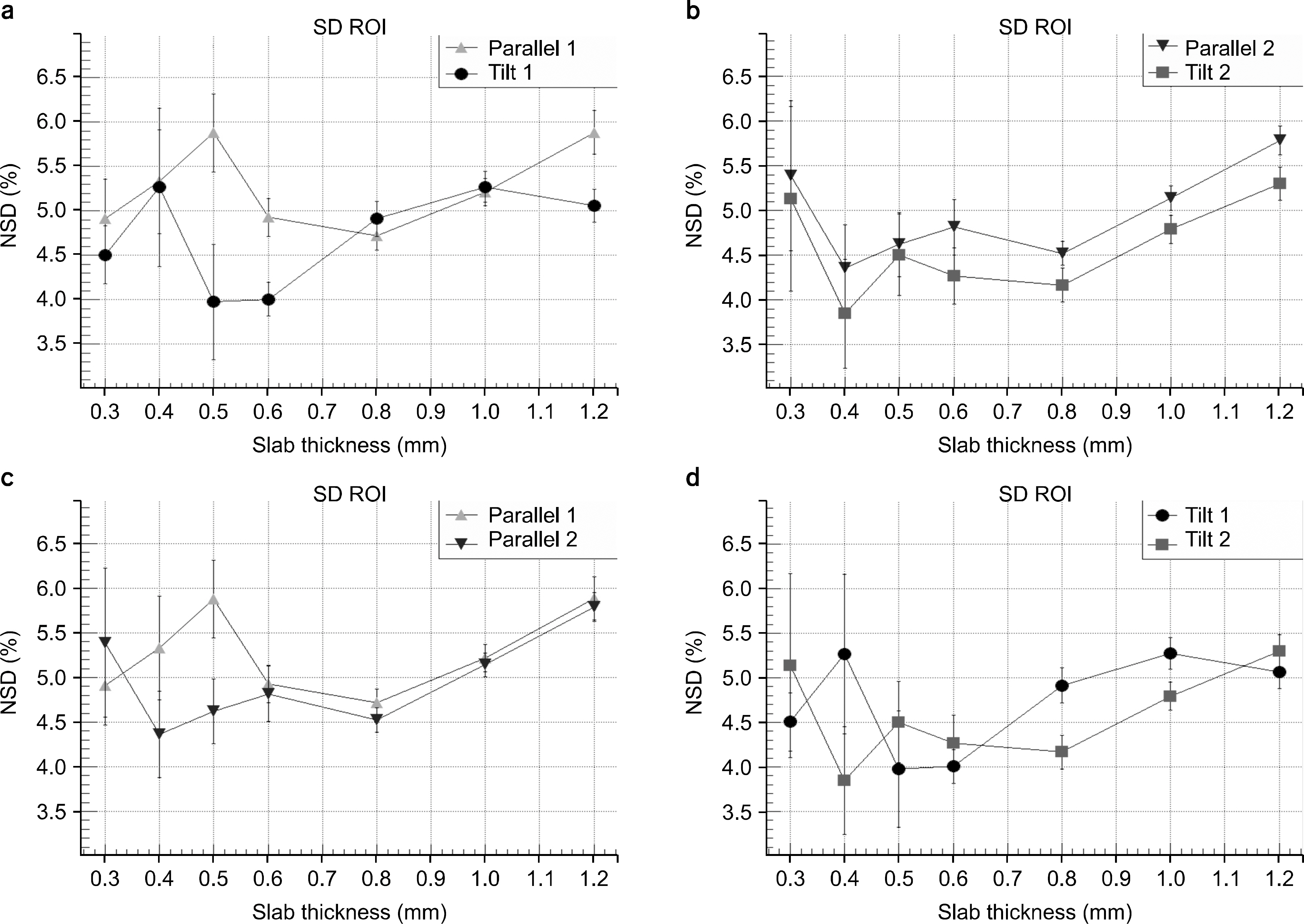
Fig. 4. Normalized standard deviation of the region of interest (ROI) in the subtracted image. Parallel 1 (triangle) and Tilt 1 (circle) are compared in (a), Parallel 2 (inverted triangle) and Tilt 2 (square) are compared in (b), Parallel 1 and 2 are compared in (c), and Tilt 1 and 2 are compared in (d).
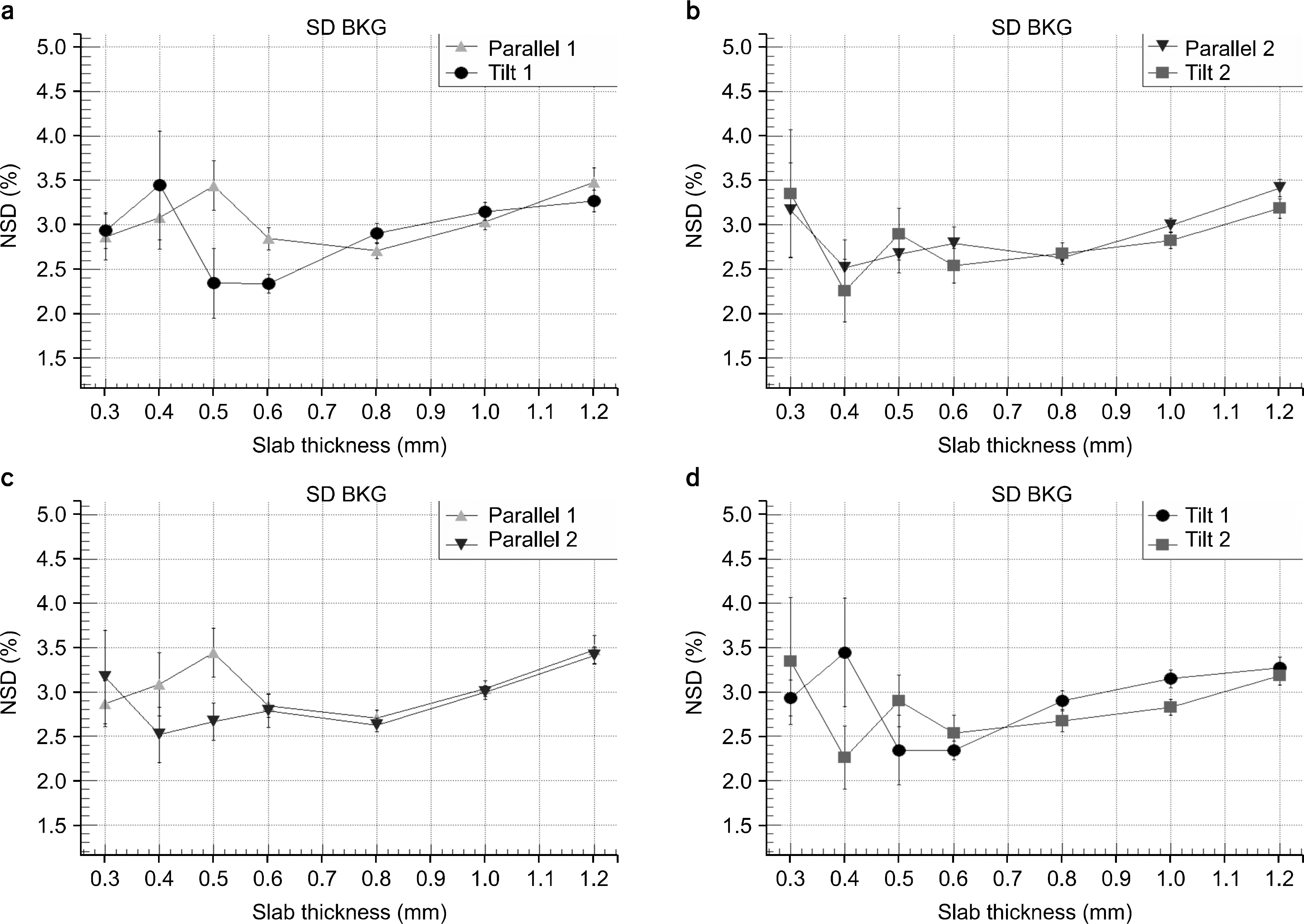
Fig. 5. Normalized standard deviation of the background (BKG) region in the subtracted image.

Fig. 6. Normalized standard deviation of the subtracted image including both ROI and BKG.
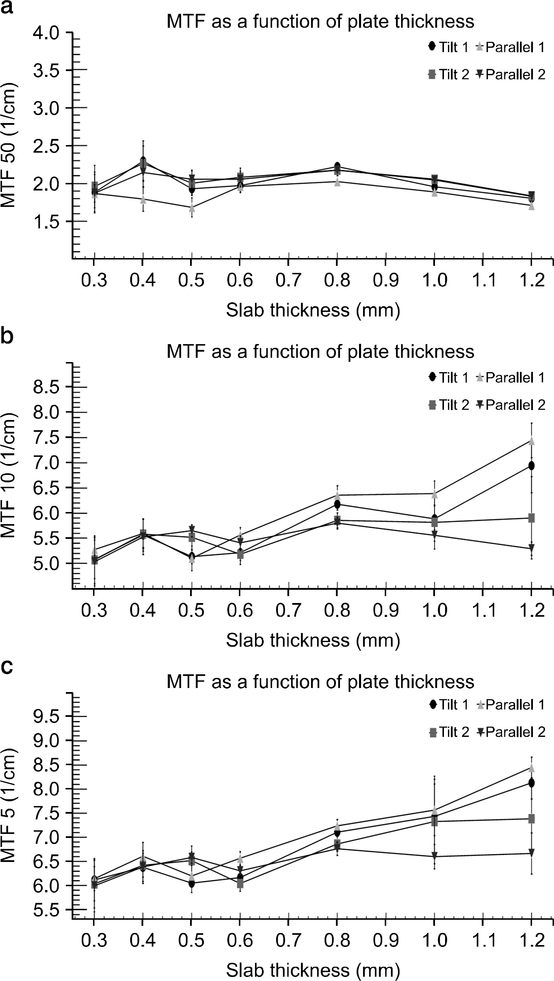
Fig. 7. MTFs as a function of sheet thickness. MTF 50 (a), MTF 10 (b), and MTF 5 (c) for Tilt 1, Tilt 2, Parallel 1, and Parallel 2 cases are presented.
Reference
-
References
1. Boone JM. Determination of the presampled MTF in computed tomography. Medical Physics. 28(3):356. 2001.
Article2. Garayoa J, Castro P. A study on image quality provided by a kilovoltage cone-beam computed tomography. J Appl Clin Med Phys. 14(1):3888. 2013.
Article3. Villafana T. Modulation transfer function of a finite scanning microdensitometer slit. Medical Physics. 2(5):251. 1975.
Article4. Gopal A, Samant SS. Use of a line-pair resolution phantom for comprehensive quality assurance of electronic portal imaging devices based on fundamental imaging metrics. Medical Physics. 36(6):2006. 2009.
Article5. Nickoloff EL. A simplified approach for modulation transfer function determinations in computed tomography. Medical Physics. 12(4):437. 1985.
Article6. Fujita H, Tsai DY, Itoh T, Morishita J, Ueda K, Ohtsuka A. A simple method for determining the modulation transfer function in digital radiography. IEEE Trans Med Imaging. 11(1):34–39. 1992.
Article7. Nakaya Y, Kawata Y, Niki N, Umetatni K, Ohmatsu H, Moriyama N. A method for determining the modulation transfer function from thick microwire profiles measured with x-ray microcomputed tomography. Medical Physics. 39(7):4347–4364. 2012.
Article8. Schwarzband G, Kiryati N. The point spread function of spi ral CT. Phys Med Biol. 50(22):5307–5322. 2005.9. Watanabe H, Honda E, Kurabayashi T. Modulation transfer function evaluation of cone beam computed tomography for dental use with the oversampling method. Dentomaxillofac Radiol. 39(1):28–32. 2010.
Article10. Yoo BG, Kweon DC, Lee JS. MTF Evaluation and Clinical Application according to the Characteristic Kernels in the Computed Tomography. Korean J Med Phy. 18(2):55–64. 2007.11. Miéville F, Beaumont S, Torfeh T, Gudinchet F, Verdun F. R.: Computed tomography commissioning programmes: how to obtain a reliable MTF with an automatic approach? Radiation Protection Dosimetry. 139(1–3):443–448. 2010.12. Villafana T. Effect of finite exposure slits in determination of the line spread function and modulation transfer function. Acta Radiol Ther Phys Biol. 16(3):281–288. 1977.
Article13. Ohkubo M, Wada S, Matsumoto T, Nishizawa K. An effective method to verify line and point spread functions measured in computed tomography. Medical Physics. 33(8):2757. 2006.
Article14. Marchand E. W.: Derivation of the Point Spread Function from the Line Spread Function. Journal of the Optical Society of America. 54(7):915–919. 1964.15. Kayugawa A, Ohkubo M, Wada S. Accurate determination of CT point-spread-function with high precision. J Appl Clin Med Phys. 14 (4) (. 2013.16. Hyer DE, Serago CF, Kim S, Li JG, Hintenlang DE. An organ and effective dose study of XVI and OBI cone-beam CT systems. J Appl Clin Med Phys. 11 (2) (. 2010.17. Yagi M, Ueguchi T, Koizumi M, et al. Gemstone spectral imaging: determination of CT to ED conversion curves for radiotherapy treatment planning. J Appl Clin Med Phys. 14(5):173–186. 2013.
Article
- Full Text Links
-
- Actions
-
Cited
- CITED
-
- Close
- Share
-
- Similar articles
-
- A study on the rotational therapy employing 60-Co teletherapy unit with aluminum therapy table
- A study on assessment of bone mass from aluminum-equivalent image by digital imaging system
- Immunogenicity of Aujesky's disease virus isolated from the diseased piglets in Korea I. immunogenicity of the inactivated Aujesky's disease virus with aluminum hydroxide gel adjuvant
- Serum Aluminum Level in End-Stage Renal Failure
- Comparing Clinical Results after Intraocular Lens Implantation Surgery Using Three Other Aspheric Lenses
