Korean J Orthod.
2011 Aug;41(4):268-279. 10.4041/kjod.2011.41.4.268.
Influence of surface treatment on the insertion pattern of self-drilling orthodontic mini-implants
- Affiliations
-
- 1Department of Orthodontics, School of Dentistry, Wonkwang University, Wonkwang Dental Research Institute, Korea. sangkim@wonkwang.ac.kr
- KMID: 2274261
- DOI: http://doi.org/10.4041/kjod.2011.41.4.268
Abstract
OBJECTIVE
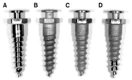
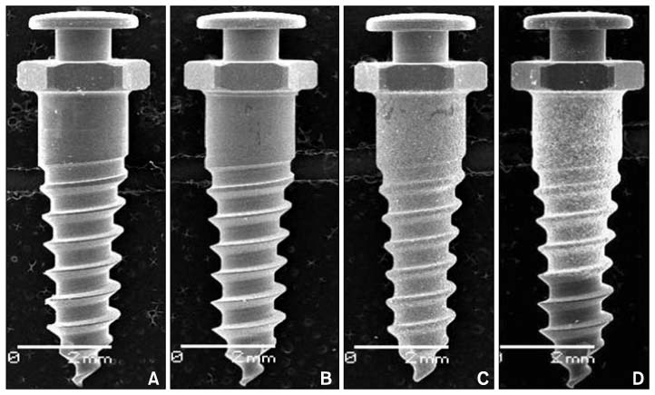
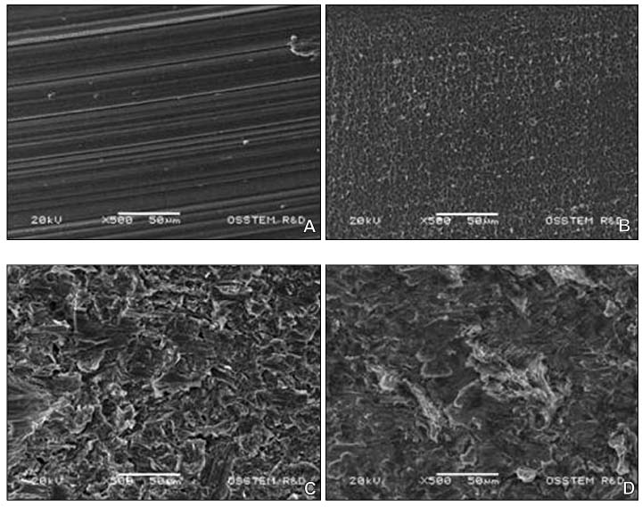
The purpose of this study was to compare self-drilling orthodontic mini-implants of different surfaces, namely, machined (untreated), etched (acid-etched), RBM (treated with resorbable blasting media) and hybrid (RBM + machined), with respect to the following criteria: physical appearance of the surface, measurement of surface roughness, and insertion pattern.
METHODS
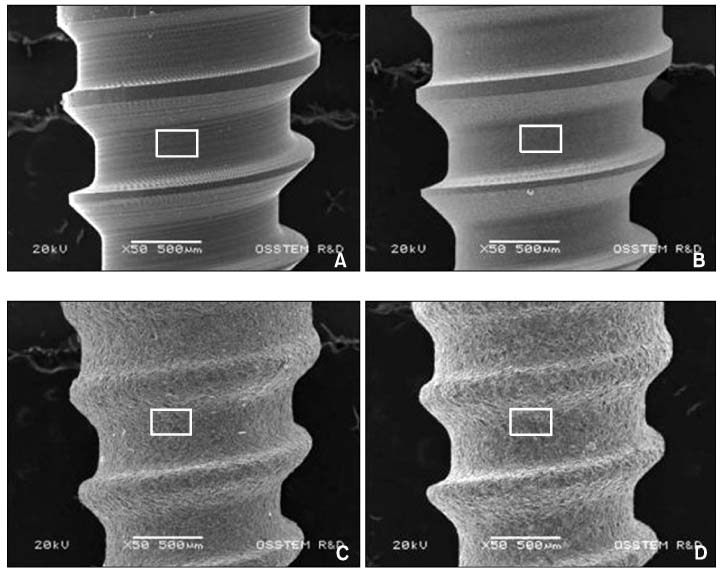
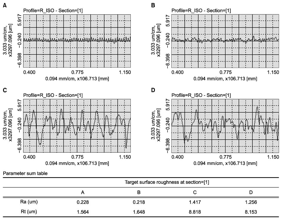
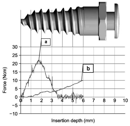
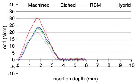
Self-drilling orthodontic mini-implants (Osstem implant, Seoul, Korea) with the abovementioned surfaces were obtained. Surface roughness was measured by using a scanning electron microscope and surface-roughness-testing machine, and torque patterns and vertical loadings were measured during continuous insertion of mini-implants into artificial bone (polyurethane foam) by using a torque tester of the driving-motor type (speed, 12 rpm).
RESULTS
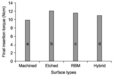
The mini-implants with the RBM, hybrid, and acid-etched surfaces had slightly increased maximum insertion torque at the final stage (p < 0.05). Implants with the RBM surface had the highest vertical load for insertion (p < 0.05). Testing for surface roughness revealed that the implants with the RBM and hybrid surfaces had higher Ra values than the others (p < 0.05). Scanning electron microscopy showed that the implants with the RBM surface had the roughest surface.
CONCLUSIONS
Surface-treated, self-drilling orthodontic mini-implants may be clinically acceptable, if controlled appropriately.
Figure
Cited by 1 articles
-
Bone cutting capacity and osseointegration of surface-treated orthodontic mini-implants
Ho-Young Kim, Sang-Cheol Kim
Korean J Orthod. 2016;46(6):386-394. doi: 10.4041/kjod.2016.46.6.386.
Reference
-
1. Kanomi R. Mini-implant for orthodontic anchorage. J Clin Orthod. 1997. 31:763–767.2. Chen Y, Shin HI, Kyung HM. Biomechanical and histological comparison of self-drilling and self-tapping orthodontic microimplants in dogs. Am J Orthod Dentofacial Orthop. 2008. 133:44–50.
Article3. Chen Y, Kyung HM, Zhao WT, Yu WJ. Critical factors for the success of orthodontic mini-implants: a systematic review. Am J Orthod Dentofacial Orthop. 2009. 135:284–291.
Article4. Crismani AG, Bertl MH, Celar AG, Bantleon HP, Burstone CJ. Miniscrews in orthodontic treatment: review and analysis of published clinical trials. Am J Orthod Dentofacial Orthop. 2010. 137:108–113.
Article5. Park JS, Yu W, Kyung HM, Kwon OW. Finite element analysis of cortical bone strain induced by self-drilling placement of orthodontic microimplant. Korean J Orthod. 2009. 39:203–212.
Article6. Kravitz ND, Kusnoto B. Risks and complications of orthodontic miniscrews. Am J Orthod Dentofacial Orthop. 2007. 131:4 Suppl. S43–S51.
Article7. Kuroda S, Yamada K, Deguchi T, Hashimoto T, Kyung HM, Takano-Yamamoto T. Root proximity is a major factor for screw failure in orthodontic anchorage. Am J Orthod Dentofacial Orthop. 2007. 131:4 Suppl. S68–S73.
Article8. Lee YK, Kim JW, Baek SH, Kim TW, Chang YI. Root and bone response to the proximity of a mini-implant under orthodontic loading. Angle Orthod. 2010. 80:452–458.
Article9. Poggio PM, Incorvati C, Velo S, Carano A. "Safe zones": a guide for miniscrew positioning in the maxillary and mandibular arch. Angle Orthod. 2006. 76:191–197.10. Lim SA, Cha JY, Hwang CJ. Insertion torque of orthodontic miniscrews according to changes in shape, diameter and length. Angle Orthod. 2008. 78:234–240.
Article11. Kim JW, Baek SH, Kim TW, Chang YI. Comparison of stability between cylindrical and conical type mini-implants. Mechanical and histological properties. Angle Orthod. 2008. 78:692–698.
Article12. Cho IS. The initial stability of mini-implants according to surface treatment method (thesis). 2008. Seoul: Seoul National University.13. Kim SH, Lee SJ, Cho IS, Kim SK, Kim TW. Rotational resistance of surface-treated mini-implants. Angle Orthod. 2009. 79:899–907.
Article14. Mo SS, Kim SH, Kook YA, Jeong DM, Chung KR, Nelson G. Resistance to immediate orthodontic loading of surface-treated mini-implants. Angle Orthod. 2010. 80:123–129.
Article15. Kasemo B, Lausmaa J. Aspects of surface physics on titanium implants. Swed Dent J Suppl. 1985. 28:19–36.16. Chehroudi B, Gould TR, Brunette DM. Titanium-coated micromachined grooves of different dimensions affect epithelial and connective-tissue cells differently in vivo. J Biomed Mater Res. 1990. 24:1203–1219.
Article17. Le Guéhennec L, Soueidan A, Layrolle P, Amouriq Y. Surface treatments of titanium dental implants for rapid osseointegration. Dent Mater. 2007. 23:844–854.
Article18. Cochran DL, Nummikoski PV, Higginbottom FL, Hermann JS, Makins SR, Buser D. Evaluation of an endosseous titanium implant with a sandblasted and acid-etched surface in the canine mandible: radiographic results. Clin Oral Implants Res. 1996. 7:240–252.
Article19. Motoyoshi M, Hirabayashi M, Uemura M, Shimizu N. Recommended placement torque when tightening an orthodontic mini-implant. Clin Oral Implants Res. 2006. 17:109–114.
Article20. Blumenthal NC, Cosma V. Inhibition of apatite formation by titanium and vanadium ions. J Biomed Mater Res. 1989. 23:A1 Suppl. 13–22.
Article
- Full Text Links
- Actions
-
Cited
- CITED
-
- Close
- Share
- Similar articles
-
- Geometrical design characteristics of orthodontic mini-implants predicting maximum insertion torque
- The effects of different pilot-drilling methods on the mechanical stability of a mini-implant system at placement and removal: a preliminary study
- Bone cutting capacity and osseointegration of surface-treated orthodontic mini-implants
- Three-dimensional finite element analysis for stress distribution on the diameter of orthodontic mini-implants and insertion angle to the bone surface
- Effect of cutting flute length and shape on insertion and removal torque of orthodontic mini-implants

