Screw-Home Movement of the Tibiofemoral Joint during Normal Gait: Three-Dimensional Analysis
- Affiliations
-
- 1Department of Orthopedic Surgery, Eulji University College of Medicine, Daejeon, Korea. oskkj@eulji.ac.kr
- KMID: 2234083
- DOI: http://doi.org/10.4055/cios.2015.7.3.303
Abstract
- BACKGROUND
The purpose of this study was to evaluate the screw-home movement at the tibiofemoral joint during normal gait by utilizing the 3-dimensional motion capture technique.
METHODS
Fifteen young males and fifteen young females (total 60 knee joints) who had no history of musculoskeletal disease or a particular gait problem were included in this study. Two more markers were attached to the subject in addition to the Helen-Hayes marker set. Thus, two virtual planes, femoral coronal plane (P(f)) and tibial coronal plane (P(t)), were created by Skeletal Builder software. This study measured the 3-dimensional knee joint movement in the sagittal, coronal, and transverse planes of these two virtual planes (P(f) and P(t)) during normal gait.
RESULTS
With respect to kinematics and kinetics, both males and females showed normal adult gait patterns, and the mean difference in the temporal gait parameters was not statistically significant (p > 0.05). In the transverse plane, the screw-home movement occurred as expected during the pre-swing phase and the late-swing phase at an angle of about 17degrees. However, the tibia rotated externally with respect to the femur, rather than internally, while the knee joint started to flex during the loading response (paradoxical screw-home movement), and the angle was 6degrees.
CONCLUSIONS
Paradoxical screw-home movement may be an important mechanism that provides stability to the knee joint during the remaining stance phase. Obtaining the kinematic values of the knee joint during gait can be useful in diagnosing and treating the pathological knee joints.
Keyword
MeSH Terms
Figure
-

Fig. 1 Anterior (A) and posterior (B) photographs show that 9-mm passive reflective markers were attached by using the Helen-Hayes method, and additional markers were attached to the medial and lateral condyles of the proximal tibia, on which the medial and lateral collateral ligaments are attached.
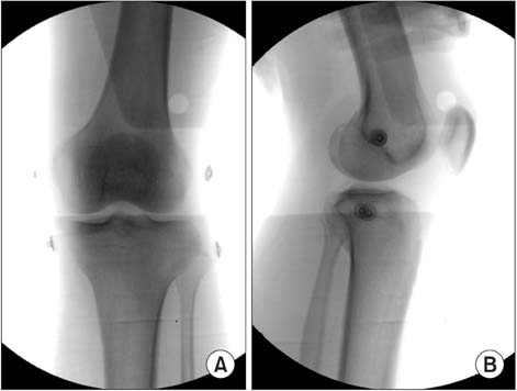
Fig. 2 Anteroposterior (A) and lateral (B) radiographs show that the marker was attached to the medial and lateral condyles of the femur and the tibia. The marker on the lateral tibial condyle was positioned just over the top of the fibular head while the marker on the medial tibial condyle was positioned over the bony surface on which the medial collateral ligament is inserted. It was mostly at the same level as that of the lateral tibial condyle marker.
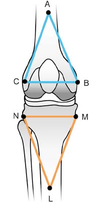
Fig. 3 This schematic image shows the two virtual planes (the femoral coronal plane and tibial coronal plane) created using the SKB program. A: distal thigh, B: medial femoral epicondyle, C: lateral femoral epicondyle, L: shank, M: medial tibial condyle, N: fibular head.

Fig. 4 These graphs show kinematics of the knee joint during gait. (A) While the knee joint was flexed approximately 15° during the loading response, the tibia was externally rotated around the femur about 6° (green line and black arrow). (B) This amount of tibial rotation was maintained during the mid-stance phase (green line and black arrow). (C) As the knee reached full extension in the late-swing phase, the tibia was then rotated externally by 17°; thus, it almost reached the neutral position (green line and black arrow). Rz: rotational degrees in the sagittal plane, negative value is the extension angle and positive value is the flexion angle, Rx: rotational degrees in the coronal plane, negative value is the extension angle and positive value is the flexion angle, negative value is the valgus angle and positive value is the varus angle, Ry: rotational degrees in the transverse plane, negative value is the external rotation angle and positive value is the internal rotation angle.
Reference
-
1. Goodfellow J, O'Connor J. The mechanics of the knee and prosthesis design. J Bone Joint Surg Br. 1978; 60(3):358–369.2. Bytyqi D, Shabani B, Lustig S, Cheze L, Karahoda Gjurgjeala N, Neyret P. Gait knee kinematic alterations in medial osteoarthritis: three dimensional assessment. Int Orthop. 2014; 38(6):1191–1198.3. Ishii Y, Terajima K, Terashima S, Koga Y. Three-dimensional kinematics of the human knee with intracortical pin fixation. Clin Orthop Relat Res. 1997; (343):144–150.4. Wretenberg P, Ramsey DK, Nemeth G. Tibiofemoral contact points relative to flexion angle measured with MRI. Clin Biomech (Bristol, Avon). 2002; 17(6):477–485.5. Asano T, Akagi M, Tanaka K, Tamura J, Nakamura T. In vivo three-dimensional knee kinematics using a biplanar imagematching technique. Clin Orthop Relat Res. 2001; (388):157–166.6. DeFrate LE, Sun H, Gill TJ, Rubash HE, Li G. In vivo tibiofemoral contact analysis using 3D MRI-based knee models. J Biomech. 2004; 37(10):1499–1504.7. Udagawa K, Niki Y, Enomoto H, Toyama Y, Suda Y. Factors influencing graft impingement on the wall of the intercondylar notch after anatomic double-bundle anterior cruciate ligament reconstruction. Am J Sports Med. 2014; 42(9):2219–2225.8. Lee TQ. Biomechanics of hyperflexion and kneeling before and after total knee arthroplasty. Clin Orthop Surg. 2014; 6(2):117–126.9. Yang JH, Chang M, Kwak DS, Jang KM, Wang JH. In vivo three-dimensional imaging analysis of femoral and tibial tunnel locations in single and double bundle anterior cruciate ligament reconstructions. Clin Orthop Surg. 2014; 6(1):32–42.10. Moro-oka TA, Hamai S, Miura H, et al. Can magnetic resonance imaging-derived bone models be used for accurate motion measurement with single-plane three-dimensional shape registration? J Orthop Res. 2007; 25(7):867–872.11. You BM, Siy P, Anderst W, Tashman S. In vivo measurement of 3-D skeletal kinematics from sequences of biplane radiographs: application to knee kinematics. IEEE Trans Med Imaging. 2001; 20(6):514–525.12. Komistek RD, Dennis DA, Mahfouz M. In vivo fluoroscopic analysis of the normal human knee. Clin Orthop Relat Res. 2003; (410):69–81.13. Fregly BJ, Rahman HA, Banks SA. Theoretical accuracy of model-based shape matching for measuring natural knee kinematics with single-plane fluoroscopy. J Biomech Eng. 2005; 127(4):692–699.14. Moro-oka TA, Hamai S, Miura H, et al. Dynamic activity dependence of in vivo normal knee kinematics. J Orthop Res. 2008; 26(4):428–434.15. Kadaba MP, Ramakrishnan HK, Wootten ME. Measurement of lower extremity kinematics during level walking. J Orthop Res. 1990; 8(3):383–392.16. Hill PF, Vedi V, Williams A, Iwaki H, Pinskerova V, Freeman MA. Tibiofemoral movement 2: the loaded and unloaded living knee studied by MRI. J Bone Joint Surg Br. 2000; 82(8):1196–1198.17. Kozanek M, Hosseini A, Liu F, et al. Tibiofemoral kinematics and condylar motion during the stance phase of gait. J Biomech. 2009; 42(12):1877–1884.18. Qi W, Hosseini A, Tsai TY, Li JS, Rubash HE, Li G. In vivo kinematics of the knee during weight bearing high flexion. J Biomech. 2013; 46(9):1576–1582.19. Koo S, Andriacchi TP. The knee joint center of rotation is predominantly on the lateral side during normal walking. J Biomech. 2008; 41(6):1269–1273.20. Karrholm J, Brandsson S, Freeman MA. Tibiofemoral movement 4: changes of axial tibial rotation caused by forced rotation at the weight-bearing knee studied by RSA. J Bone Joint Surg Br. 2000; 82(8):1201–1203.21. Lafortune MA, Cavanagh PR, Sommer HJ 3rd, Kalenak A. Three-dimensional kinematics of the human knee during walking. J Biomech. 1992; 25(4):347–357.
- Full Text Links
-
- Actions
-
Cited
- CITED
-
- Close
- Share
-
- Similar articles
-
- Translational Movement of the Tibiofemoral Joint in Normal Gait: 3-Dimensional Measurement
- Gait Analysis after Total Knee Arthroplasty
- Effect of Korean Traditional Dance Movement Training on Balance, Gait and Leg Strength in Home Bound Elderly Women
- A New Method in the Measurement of Tibiofemoral Angle
- Detection and Quantification of Screw-Home Movement Using Nine-Axis Inertial Sensors
