A Smart Setup for Craniospinal Irradiation
- Affiliations
-
- 1Department of Radiation Oncology, Mayo Clinic, Jacksonville, Florida, USA. Peterson.jennifer2@mayo.edu
- 2Department of Radiation Oncology, Virginia Commonwealth University, Richmond, Virginia, USA.
- KMID: 1910563
- DOI: http://doi.org/10.14316/pmp.2013.24.4.230
Abstract
- Our purpose is to present a novel technique for delivering craniospinal irradiation in the supine position using a perfect match, field-in-field (FIF) intrafractional feathering, and simple forward-optimization technique. To achieve this purpose, computed tomography simulation was performed with patients in the supine position. Half-beam, blocked, opposed, lateral, cranial fields with a collimator rotation were matched to the divergence of the superior border of an upper-spinal field. Fixed field parameters were used, and the isocenter of the upper-spinal field was placed at the same source-to-axis distance (SAD), 20 cm inferior to the cranial isocenter. For a lower-spinal field, the isocenter was placed 40 cm inferior to the cranial isocenter at a constant SAD. Both gantry and couch rotations for the lower-spinal field were used to achieve perfect divergence match with the inferior border of the upper-spinal field. A FIF technique was used to feather the craniospinal and spinal-spinal junction daily by varying the match line over 2 cm. The dose throughout the target volume was modulated using the FIF simple forward optimization technique to obtain homogenous coverage. Daily, image-guided therapy was used to assure and verify the setup. This supine-position, perfect match craniospinal irradiation technique with FIF intrafractional feathering and dose modulation provides a simple and safe way to deliver treatment while minimizing dose inhomogeneity.
Figure
-
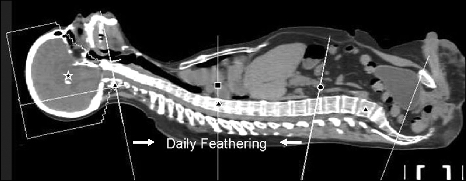
Fig. 1. Sagittal representation of the cranial field, upper-spinal field, and lower-spinal field, with each isocenter at a constant source-to-axis distance (illustrated by the star, square, and circle, respectively). Calculation points for each field are indicated by triangles.
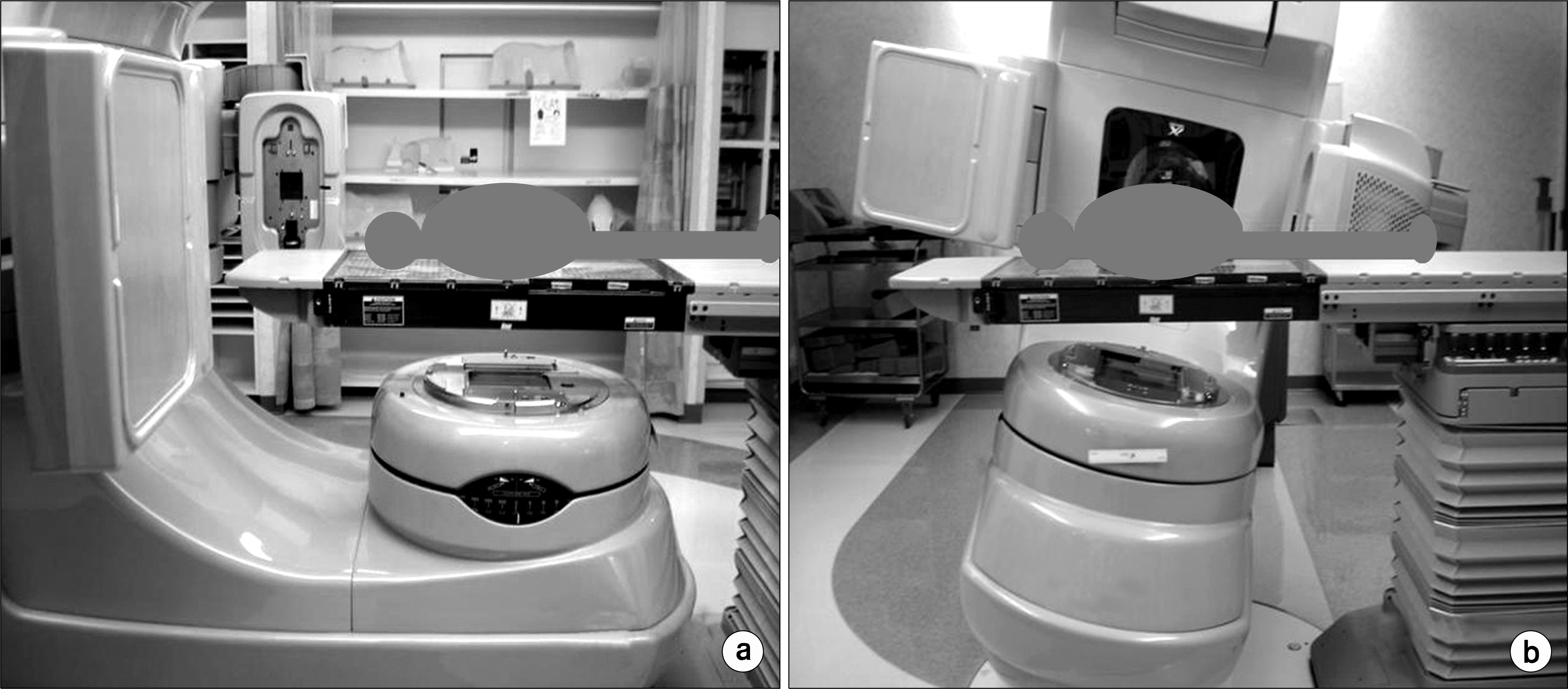
Fig. 2. Couch and gantry rotation for the spinal fields. (a) Upper spine (couch, 0o; gantry, 180o). (b) Lower spine (couch, 270o; gantry, 191o).
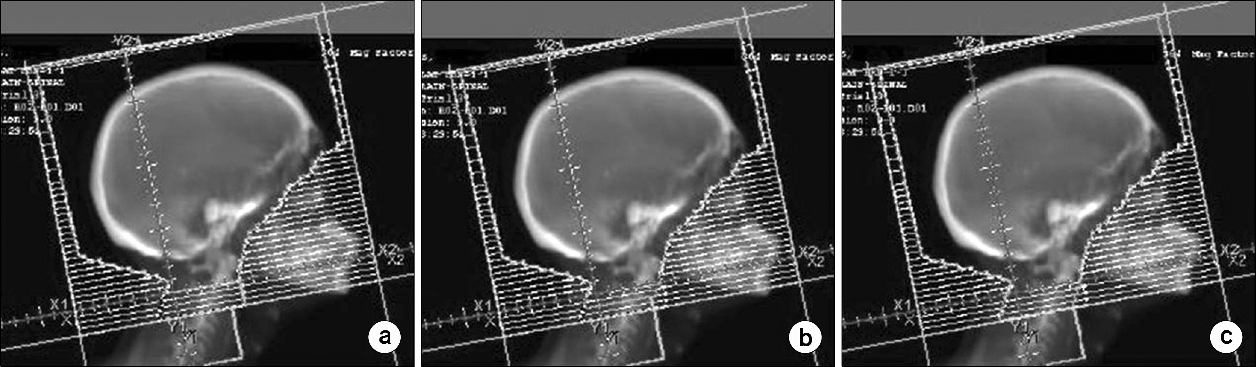
Fig. 3. (a) Cranial treatment field. (b) and (c), Illustration of the field-in-field technique used to feather the match of the craniospinal junction.
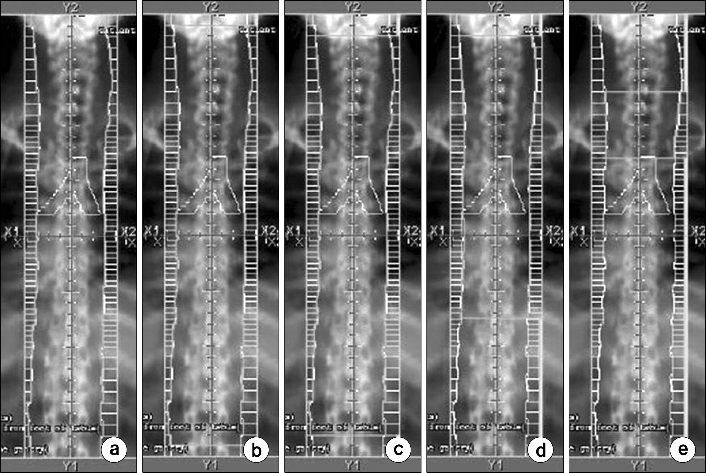
Fig. 4. (a) Upper-spinal treatment field. (b) and (c), Illustration of the field-in-field technique used to feather the match of the craniospinal junction superiorly and the spinal-spinal junction inferiorly. (d) and (e) Illustration of the field- infield technique used to modulate the dose throughout the upper-spinal field.
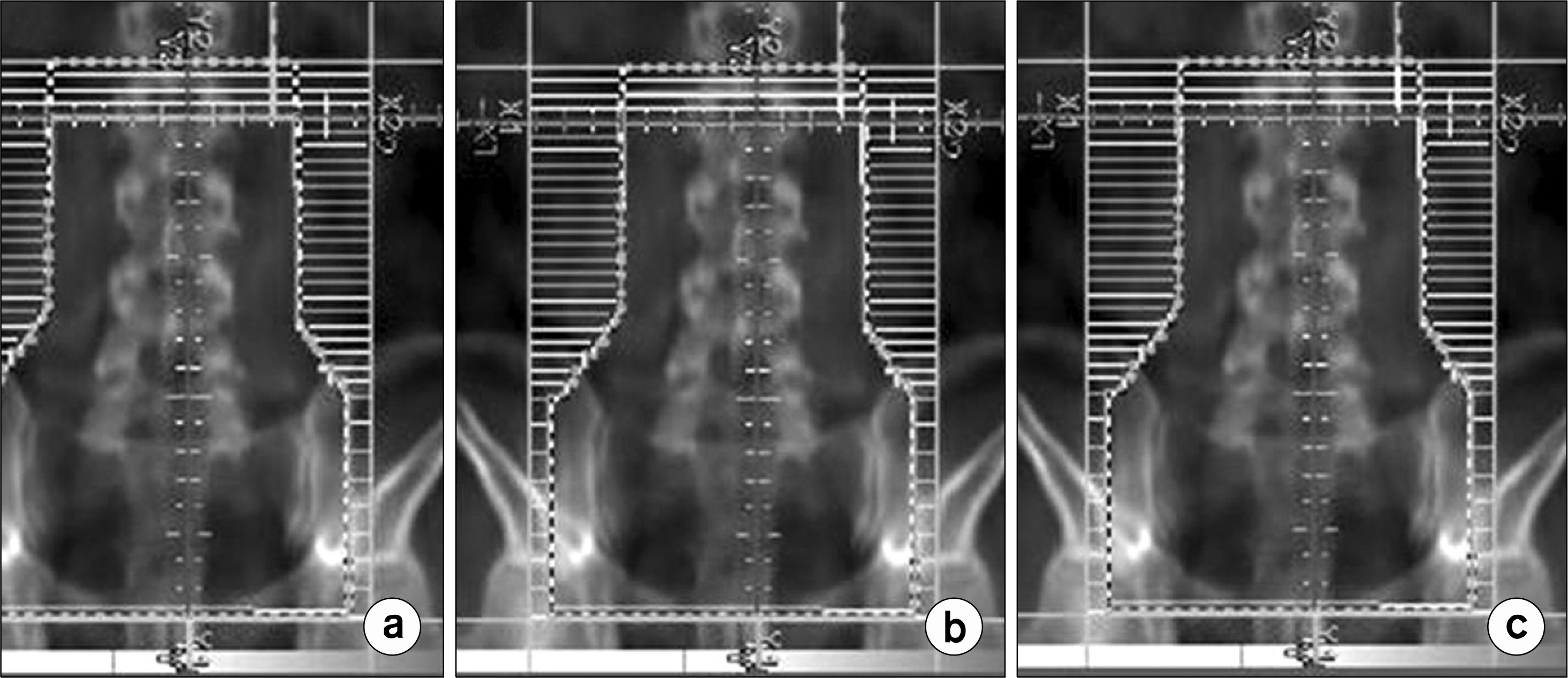
Fig. 5. (a) Lower-spinal treatment field. (b) and (c), Illustration of the field-in-field technique used to feather the match of the spinal spinal junction.
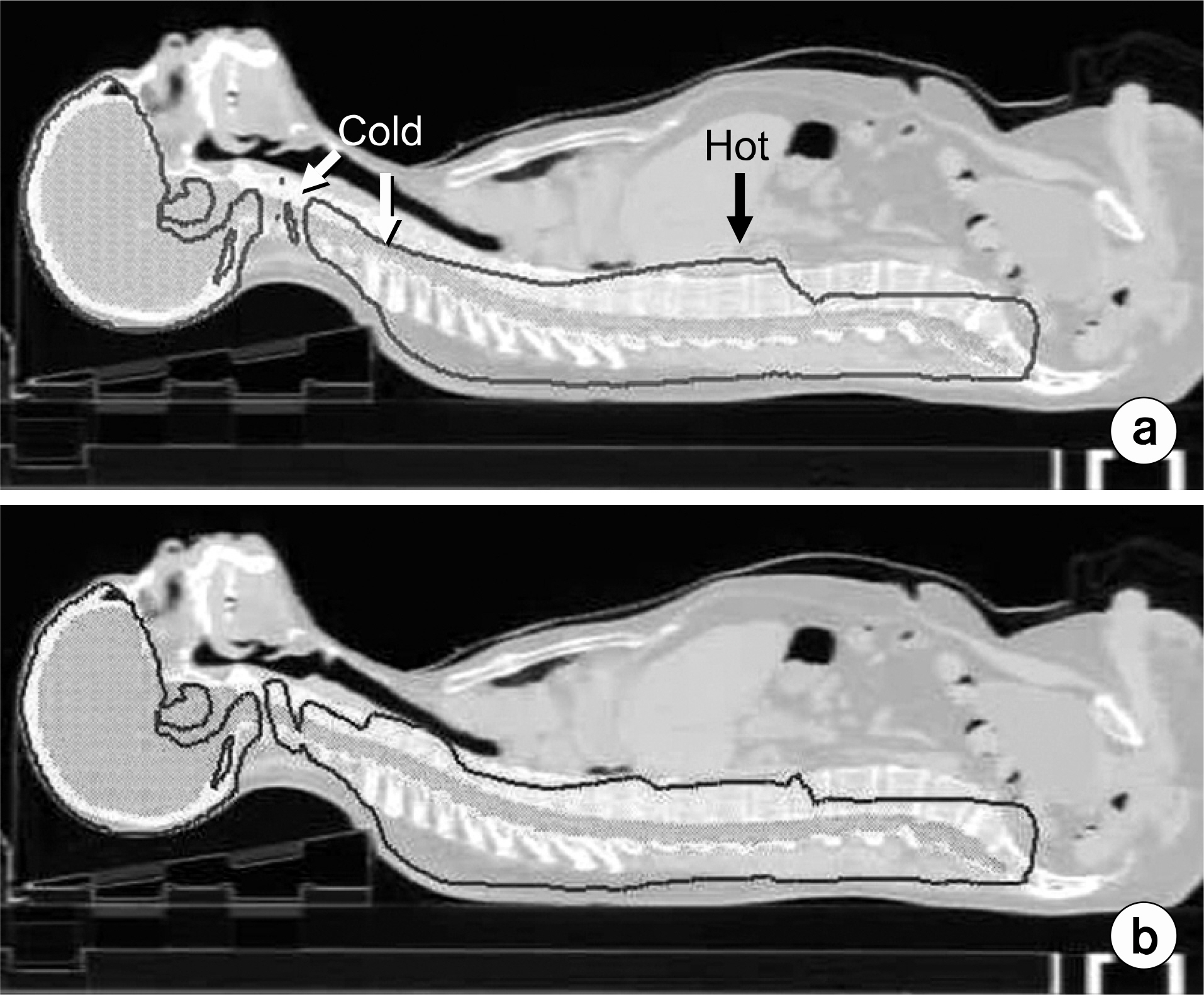
Fig. 6. Sagittal reconstruction of dose distribution. (a) Without dose modulation. (b) With field-in-field dose modulation. Target volume is green, 100% isodose line is red.
Reference
-
1. Parker WA, Freeman CR. A simple technique for craniospinal radiotherapy in the supine position. Radiother Oncol. 78(2):217–222. 2006; Epub 2005 Dec 5.
Article2. Munshi A, Jalali R. A simple technique of supine craniospinal irradiation. Med Dosim. 33(1):1–5. 2008.
Article3. Hawkins RB. A simple method of radiation treatment of craniospinal fields with patient supine. Int J Radiat Oncol Biol Phys. 49(1):261–264. 2001.
Article4. South M, Chiu JK, Teh BS, Bloch C, Schroeder TM, Paulino AC. Supine craniospinal irradiation using intrafractional junction shifts and field-in-field dose shaping: early experience at Methodist Hospital. Int J Radiat Oncol Biol Phys. 71(2):477–483. 2008; ). Epub 2007 Dec 31.
Article5. Yom SS, Frija EK, Mahajan A, et al. Field-in-field technique with intrafractionally modulated junction shifts for craniospinal irradiation. Int J Radiat Oncol Biol Phys. 69(4):1193–1198. 2007.
Article6. Pai Panandiker A, Ning H, Likhacheva A, et al. Craniospinal irradiation with spinal IMRT to improve target homogeneity. Int J Radiat Oncol Biol Phys. 68(5):1402–1409. 2007; Epub 2007 Apr 30.7. Parker W, Filion E, Roberge D, Freeman CR. Intensitymodulated radiotherapy for craniospinal irradiation: target volume considerations, dose constraints, and competing risks. Int J Radiat Oncol Biol Phys. 69(1):251–257. 2007.
Article8. Kusters JM, Louwe RJ, van Kollenburg PG, et al. Optimal normal tissue sparing in craniospinal axis irradiation using IMRT with daily intrafractionally modulated junction(s). Int J Radiat Oncol Biol Phys. 81(5):1405–1414. 2011.
Article9. Chang EL, Wong PF, Forster KM, Petru MD, Kowalski AV, Maor MH. Verification techniques and dose distribution for computed tomographic planned supine craniospinal radiation therapy. Med Dosim. 28(2):127–131. 2003.
Article10. Rades D, Baumann R, Bremer M, Leuwer M, Karstens JH. Application of a new verification technique allowing craniospinal irradiation in supine position. Radiother Oncol. 58(2):215–217. 2001.
Article11. Liu AK, Thornton D, Backus J, Dzingle W, Stoehr S, Newman F. Supine craniospinal irradiation setup with two spine fields. Med Dosim. 34(3):214–216. 2009; Epub 2008 Oct 7.
Article12. Huang F, Parker W, Freeman CR. Feasibility and early outcomes of supine-position craniospinal irradiation. Pediatr Blood Cancer. 54(2):322–325. 2010.
Article
- Full Text Links
-
- Actions
-
Cited
- CITED
-
- Close
- Share
-
- Similar articles
-
- Two Cases of Thyroid Tumor after Radiation Therapy of Primary Malignancy
- CT Simulation Technique for Craniospinal Irradiation in Supine Position
- The Effect of Intermittent Craniospinal Irradiation and Intrathecal Chemotherapy for Overt Meningeal Leukemia
- Radiotherapy Results of pineal Tumors
- A case report on successful pregnancy and delivery in a medulloblastoma patient
